- Subscribe to RSS Feed
- Mark Topic as New
- Mark Topic as Read
- Float this Topic for Current User
- Bookmark
- Subscribe
- Mute
- Printer Friendly Page
NI ELVIS Power Electronics Trainer - Hands-On Experiential Learning System
01-17-2012 09:53 AM
- Mark as New
- Bookmark
- Subscribe
- Mute
- Subscribe to RSS Feed
- Permalink
- Report to a Moderator
The software installers and code for this trainer/research system are now available for download.
A new Voltage Divider Board for the NI ELVIS Power Electronics Trainer is now available. This board includes voltage dividers and connectors that simplifies wiring.
This site shows a new hands-on switched-mode power supply (SMPS) experiential learning system and curriculum based on the National Instruments ELVIS platform and a 3-phase 6-pack inverter intelligent power module (IPM).
The experimental measurement capabilities of NI ELVIS combine with the new interactive co-simulation environment of LabVIEW and Multisim to create an exciting new platform for learning power electronics. The idea is that through experimentation with the virtual and physical circuits, students can gain an intuitive understanding that's not possible without this type of personal, interaction and experimentation.
Students or universities that cannot afford the physical hardware can still gain much of the experiental learning through the LabVIEW/Multisim co-simulation tools, which behave just like the real-circuits but can be executed on any laptop computer. If the hardware is available, student start by designing their switched-mode power supply (SMPS) circuits at home using co-simulation, then come into the lab and build the physical circuits and compare the results. The NI ELVIS Digital Electronics FPGA board is a great platform for learning power electronics.
The entire SMPS circuit can be built from scratch on the protoboard area using discrete components, or the 3-built in quarter bridge transistor-diode circuits of the 6-pack inverter can be used. If this is the case, the students design and build only the RLC filter stage for their SMPS. Rather than having a pre-built circuit for everything, the students can make their own three phase loads by dropping the RLC values they designed at home onto the ELVIS breadboard area.
A 10X step-down wall transformer is used to supply the single-phase AC power for the system, resulting in a ~17 Vdc DC Link voltage after passing through the full bridge rectifier circuit on the system. Thus all the voltages are safe to touch. The inverter evaluation board also contains 0.1 Ohm shunt resistors on the bottom of the 3 IGBT quarter bridge legs for current sensing. Resistor dividers are used on the NI ELVIS Digital Electronics FPGA Boards so that all 3-phase voltages (filtered and unfiltered) are measured, along with the Grid Voltage, DC_Link or Neutral Voltage, and input currents. The three-phase power waveforms are then analyzed using the new NI Electrical Power Measurement Suite.
This curriculum material will be added to the cosimulation design guide. Please share your ideas and feedback.
Below is a photo of the trainer setup. It uses the ST Micro STEVAL-IHM027V1 3-phase motor control demonstration board featuring IGBT intelligent power module (IPM) containing a STGIPS10K60A (10 A, 600 V, 3-phase IGBT IPM inverter bridge with control ICs for gate driving and free-wheeling diodes), available for less than $100. It uses the $259.00 USD NI Digital Electronics FPGA Board for ELVIS 781025-01, which contains a small Spartan-3E 500E FPGA (XC3S500E).
You can use it as a half bridge, H-bridge single-phase inverter, or 6-switch three phase inverter. It also contains a single-phase full bridge rectifier, regenerative chopper brake and various built in protection circuits. For circuits in which you wish to learn about discrete TO-220 style IGBTs or MOSFETs, you can place those components on the protoboard and each half bridge leg of the 3-leg IGBT module acts as the gate drive for the IGBT or MOSFET- just be sure to include a gate resistor. This is useful for building simple DC-to-DC SMPS circuits such as the buck, boost and flyback converter circuits. Also, the STEVAL board has inputs for hall switches, quadrature encoders, and tachometers so the same arrangement can be used for the motor/generator circuits in the co-simulation design guide.
INTRODUCTORY VIDEO
Introduction to System Design Methodology
Part One: Introduction, Buck Converter and Single-Phase Inverter Circuits
Part Two: Three-Phase Inverter Circuit
Part Three: Using Variants in Multisim to Test the Circuit without LabVIEW
SYSTEM DESCRIPTION
All of the circuits in the co-simulation design guide, soon to be renamed "power electronics design guide" can be simulated using co-simulation and then built physically using this teaching system. See below for a screenshot of the updated design guide LabVIEW project
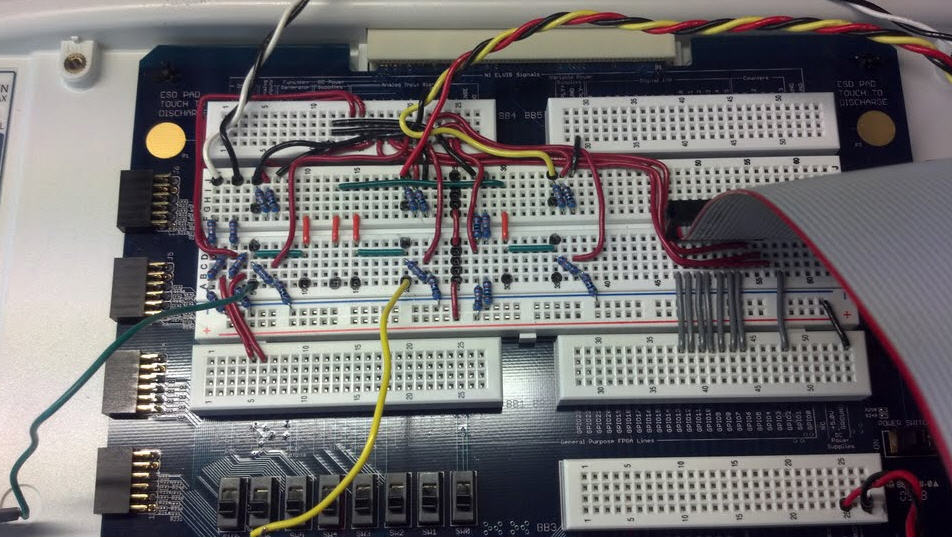
Below you can see it wired in a single-phase inverter (H bridge) configuration that uses 4 of the IGBT switches on the intelligent power module (IPM). ELVIS and the $100 eval board make for a nice clean setup. The student can place their RLC circuit design on the breadboard or hook up a three-phase PMSM motor. The 15 V power required by the evaluation board is provided by ELVIS- doing this also matches the grounds, making the ground hook ups on the scope probes unnecessary.
Notes:
- In the photo below, three inductors are shown. Actually, only two inductors are used in this single-phase H-bridge inverter experiment.
- IMPORTANT: A wall mount transformer (MGT-1240 transformer for U.S. 120 VAC, 60 Hz countries, or 11Y730 transformer for Europe and other 230 VAC, 50 Hz countries) is used to step down the 120 VAC signal from the wall to safe 12 VAC (17 VDC rectified) or 24 VAC (33.9 VDC rectified) levels on the evaluation board. This ensures there are no unsafe voltages to touch. It's nice to learn about inverters without the risk of electrocution. Bipolar capacitors are also used for safety reasons- no danger of blowing them up.

A custom ribbon cable (shown above) with row headers (shown below) is used to connect the IPM to the ELVIS breadboard. It is very easy to make if you have the connectors, row headers and a crimping tool. It makes the cabling clean and easy.
Here it is wired for a single-phase inverter. You can see the rod core inductors connected in series with phase A and B. A 100 Ohm, 1 W resistor is connected between A and B, along with a 100 uF bipolar electrolytic capacitor.

Here it is wired for a three phase inverter- you can see the three inductors for phases A, B, C, the bipolar electrolytic caps connected to ground and the 100 Ohm 1 W resistors connected to neutral.

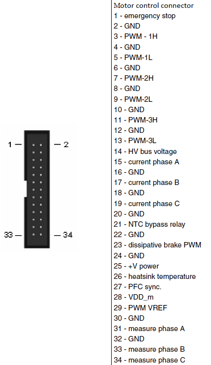
Here is the pinout of the 34-pin ribbon cable on the IPM from the STEVAL-IHM027V1 manual, page 32. The active high enable signal (emergency stop) and the active high gate drive control signals (PWM - xx) are all on the bottom row of the 34-pin ribbon cable. The gate drive command signals are all designed to support 3.3 V. Those are connected to GPIO13 to GPIO7 of the FPGA, which are raw general purpose 3.3 V digital I/O pins. Unfortunately, the NTC bypass relay (for bypassing the DC link capacitor precharge resistor) does not respond to 3.3 V signals so I don't bother wiring it to the FPGA-- that line requires a 5 V TTL signal.
Notes:
- Two ribbon cable connectors connectors are used on one end of the cable, spaced in such a way that the top and bottom rows on the 34 pin connector go to different pins on the ELVIS breadboard.
- Note that the naming for those motor position feedback signals on the STEVAL ribbon connector is "measure phase _", which is a bit confusing because you might think those signals are the phase voltages.The measure phase A, B and C signals are not the phase voltages. Those are the buffered Hall switch, encoder or tachometer outputs. To measure the phase voltages, you must use and external voltage divider.
TUTORIAL
Single-Phase H-Bridge Inverter
In the screenshot below, you can see great matching between the Multisim cosimulation results and measurements from the physical inverter using the ELVIS Scope. All signals on the screenshot below are from the cosimulation except Vab_Load_Meas (V)- the measurements for that are acquired using the ELVIS 100 MS/s scope before the simulation starts, then the Indexer function is used to play back the measured waveform during the co-simulation. You can see the waveforms match very closely.
Notes:
- I measured the DC link voltage with the ELVIS DMM to set it in the Multisim simulation. (It was 17.7 VDC.)
- I also used the ELVIS DMM to measure the actual capacitor value.
- For the other components, I just use their ideal datasheet value.
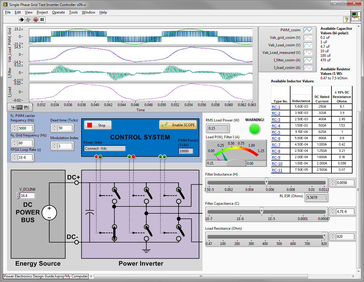
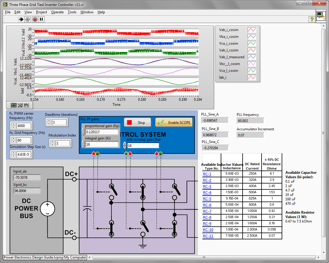
Here is a detail of the difference between the measured and co-simulated waveforms. The software interface shown in Fig. 3 shows the results of a co-simulation run in which experimental voltage measurements at the nodes Va_L and Vb_L are also acquired from an oscilloscope. The line-to-line voltage, Vab_Load, is charted on the same plot as the inverter simulation results. Due to the fidelity of the novel continuous time co-simulation interface, the signals match closely. The variable co-simulation timestep, dT (s), is automatically adjusted by the solvers to satisfy accuracy constraints.

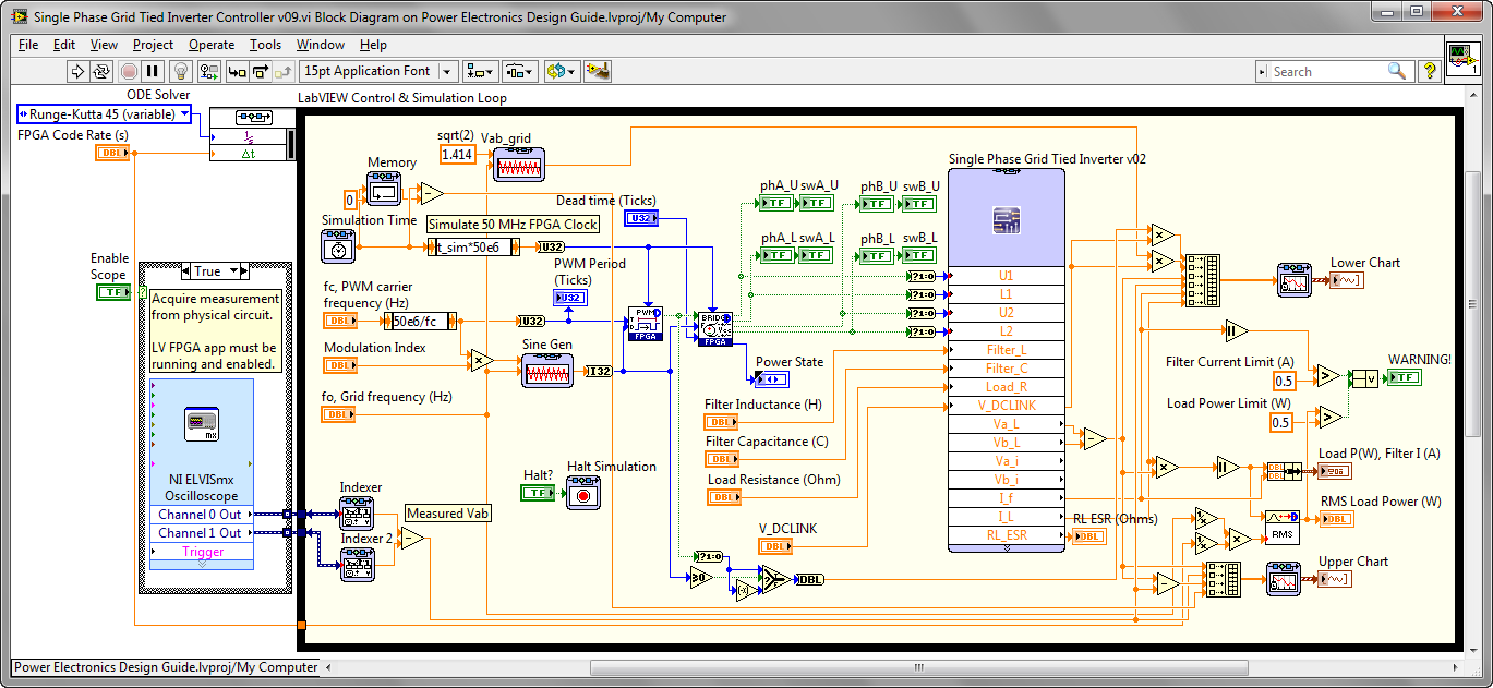
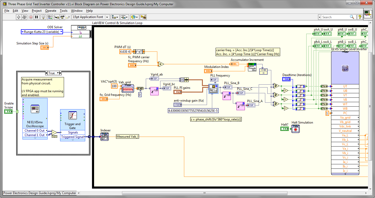
Here is the block diagram- the ELVIS scope acquires the line-to-neutral voltages, then subtract to get Vab. By using the trigger function, I can make the waveforms line up so that the simulated and measured waveforms are aligned. Note that this FPGA has a 50 MHz base clock, rather than the 40 MHz clock you might be used to.
Here is a comparison of simulated versus measured results for different component values. In this case, RL=100 Ohms, L=3.6 mH, C=4.7 uF. Despite very different waveform shapes, the experimental and co-simulation results match perfectly.

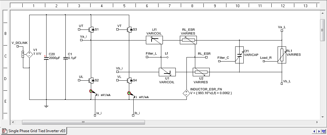
Here is the Multisim schematic. Notice that I used a voltage controlled inductor, capacitor and resistor, so the student can select the values, trying to make the output waveform look as much like a pure sine wave as possible. The students can choose their inductor and capacitor values of choice for the physical circuit. By moving the R, L, C sliders around on the LabVIEW front panel, they can try to pick the best values. There is a power meter that displays the load power- if 1 W resistors are used they must pick values that don't exceed the power rating. Also, they should look at the filter inductor and capacitor current to make sure they don't exceed the DC rated current.
This also builds confidence in the accuracy of the co-simulation tools because the waveforms look vastly different depending on what values you pick, but the simulation results will still match the physical measurements due to the accuracy of the co-simulation tools.
Infinity Physics now offers inductors specially designed for the ELVIS trainer. The inductors provide 4.3 mH of inductance with low ESR on resistance (2.2 Ohm ESR) and instrumentation taps (link). Infinity Physics also offer custom winding and manufacturing services for magnetic components such as inductors and motor windings.
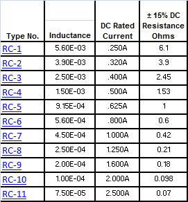
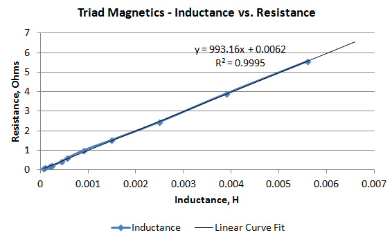
Another option for the inductors is the Triad Magnetics kits sold by Digikey as a ROD CORE RC SERIES KIT. For the inductor ESR, I put the inductance versus resistance table from the vendor into Excel and did a curve fit to get the relationship between L and R. Then I use the ABM Voltage Source component in Multisim (above) to implement the linear equation. Here is the vendor info and curve fit equation. You can buy all the inductors This way, when you change the inductance value on the LabVIEW front panel, Multisim automatically updates the ESR resistance for the inductor.
On the TRANSISTOR_DIODE components, the transistor/diode ON resistance values derived from the STGIPS10K60A 3-phase inverter (10 A, 600 V) intelligent power module (IPM) datasheet.
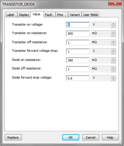
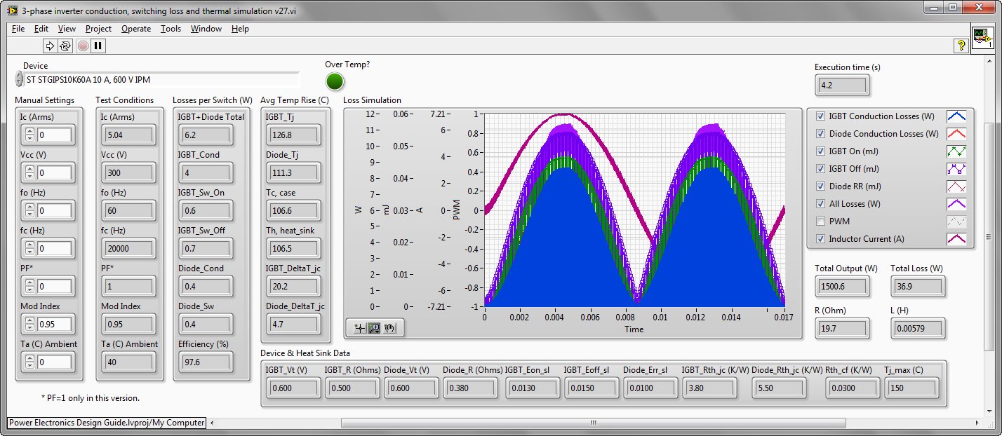
If you have the IGBTs modeled in the conduction and switching loss simulator, you can pull those on resistance numbers from the front panel (IGBT_R, Diode_R, Diode_Vt).
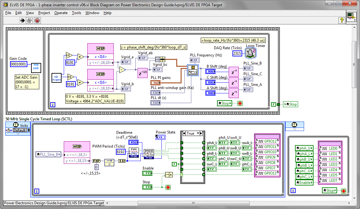
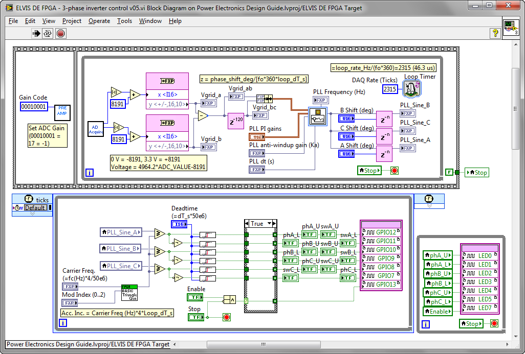
Here is the LabVIEW FPGA application running on the Spartan 3 500E FPGA on the ELVIS board. The output PWM signal is phase locked to the grid voltage (via the 10 to 1 step down transformer, so the signal is 12 VAC. That is then stepped down through a 118k/10k Ohm voltage divider.

Here is the block diagram A resistor divider is used to bring the phase A and phase B line-to-neutral voltages into the FPGA. The upper leg is 118k connected to the grid voltage (coming from the 10 to 1 step down transformer) and the lower leg is 10k Ohm, which is connected to ground. The center tap is connected to the FPGA ADC. Therefore a grid voltage of +38.94 V results in +3.3 V at the ADC, since 3.3*118/10 = 38.94).
Next the line-to-line voltage, Vgrid_ab, is calculated and a simulated Vgrid_bc is created by performing a 120 degree phase shift. The sine(phase) and cos(phase) outputs of the 3-phase PLL are used to create sinusoidal reference reference waveforms for phase A, B, and C. These reference waveforms are 32-bit signed fixed point numbers with a two bit integer wordlength- therefore the decimal point resolution of the reference waveforms is 9.31e-10. The reference sine waves vary from -1 to +1. This is converted to a 32-bit signed integer such that a value of +1 has an integer value of +8192. The PWM Period (Ticks) is based on the 50 MHz base clock of the Spartan-3 FPGA target, so a PWM Period (Ticks) = 8192 is equivalent to a PWM carrier frequency of 50e6/8192 = 6103.5 Hz. By placing the PWM generation and H-Bridge control within a 50 MHz Single Cycle Timed Loop, the PWM generation resolution is 1/50e6 = 20 ns.
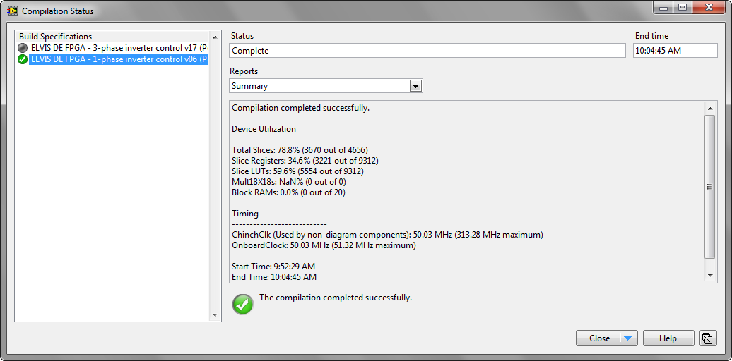
The Spartan 3 500E FPGA on the ELVIS board is a very small FPGA target- only 20 DSP cores and 4656 slices. Despite that, LabVIEW is able to compile in a way that efficiently uses the FPGA resources. Here is the compile report for the application above (sine generation, PWM, H-bridge and analog input)- it uses 79% of the slices. (The DSP multipliers (Mult18x18s) is not shown.)
Three-Phase 3-Leg Inverter
The three-phase inverter control system is also working. The Spartan-3 LX500E is a very small target to try to fit an entire 3-phase inverter control system into, mostly because the 3-phase PLL uses a lot of DSP cores. So, I rewrote the sine-triangle generator as a high precision fixed point method that has an amplitude that changes based on the modulation index.
Cosimulation Application - Experimental versus Simulated
LabVIEW FPGA 3-Phase Inverter Control Application

NI Electrical Power Measurement Suite Analysis of 3-Phase Power
MODIFYING THE CODE FOR 50 Hz POWER
Open the LabVIEW FPGA VI named "ELVIS DE FPGA - 3-phase inverter control v06.vi" under the ELVIS FPGA target in the LabVIEW Project. On the block diagram, you'll need to change the Loop Timer ticks from 2315 to 2778 ticks, and change the PLL dt (s) from 46.3e-6 to 55.5e-6. Do this on both the 3-phase and 1-phase inverter FPGA VI and then recompile.
Also examine the co-simulation examples and adjust the CD&Sim sine generator to be 50 Hz if you are using it, and make the same changes to the FPGA code in the CD&Sim loop.
CURRICULUM
Please chime in if you have thoughts or ideas. What key concepts are important to cover in the cirriculum? What are the most important design concepts, equations for students to learn? What design trade-offs and constraints are important to understand? Also, if anyone is interested in collaborating on writing the curriculum content for this please let me know.
After doing this, students can go to real-time HIL simulation of the inverters on Multicore CompactRIO for true design optimization and validation. (You need the big FPGA on Multicore CompactRIO to do this- it takes over 90 DSP multipliers.) The same inverter has a state-space model in the FPGA for real-time simulation on Multicore CompactRIO. The normalization scaling for the A, B matrix in that state-space HIL simulation reference design is being updated.
HOW TO REPLICATE THE SYSTEM
SOFTWARE INSTALLER AND CODE DOWNLOAD
Download the power electronics tools, code and videos for this experiental learning/teaching/researc...
WIRING UP AN EXISTING SYSTEM FOR 3-PHASE INVERTER
These connections assume you have an existing system and list the protoboard locations for connecting the wires.
1. Wires from the STEVAL 3-phase inverter.
| Signal | Wire Color, Pairing | Protoboard Connection Point |
|---|---|---|
| Va_grid (neutral) | White, twisted with Black | J1 |
| Vb_grid (line) | Black, twisted with White | J3 |
| Va_i | Black, twisted with Orange, Yellow, Red | J5 |
| Vb_i | Orange, twisted with Black, Yellow, Red | J20 |
| Vc_i | Yellow, twisted with Black, Orange, Red | J35 |
| Vdc_link | Red, twisted with Black, Orange, Yellow | J28 |
| +15V | Red, twisted with Black (to BB3 breadboard) | BB3:25 |
| GND | Black, twisted with Red (to BB3 breadboard) | BB3:27 |
2. Ribbon cable (carries the IGBT gate command signals from the FPGA).
Connect the ribbon cable (row closest to the key notch) to the row header located at E47:E63.
3. RLC filter components for the 3-phase circuit.
| Component | Protoboard Connection Point A | Protoboard Connection Point B |
|---|---|---|
| Inductor_A | G5 | E5 |
| Inductor_B | G20 | E20 |
| Inductor_C | G35 | E35 |
| Capacitor_A | A5 | - (Ground) |
| Capacitor_B | A15 | - (Ground) |
| Capacitor_C | A30 | - (Ground) |
| Resistor_A | A10 | + (V_neutral) |
| Resistor_B | A20 | + (V_neutral) |
| Resistor_C | A35 | + (V_neutral) |
Photo:
STEVAL-IHM027V1 JUMPER SETTINGS
If you are powering the STEVAL with 12 VAC from the transformer, the DC link voltage is not high enough to for the built in DC-to-DC converters to produce the 15 V and 5 V power rails. (I haven't tried it with a 24 VAC transformer to see if that brings the DC link high enough.) So, if you are powering with a 12 VAC transformer, make the following changes to the jumpers on the evaluation board. See page 30 in the STEVAL user manual and the relevant circuit diagrams.
J5: Remove this jumper to disconnect the 15 V DC-to-DC converter output.
J16: Remove this jumper to disconnect the 15 V DC-to-DC converter input.
J17: Add this jumper to enable 3.3 VDC power output (optional). See page 12 in STEVAL manual.
W5: Set jumper to A position to supply hall sensor/encoder connector with Vdd_m (optional)
W9: Remove this jumper so Vdd_m is not set to +5 VDC
W11: Confirm this jumper is present to set Vdd_m to +3.3 VDC
WIRING UP A NEW SYSTEM - ELVIS DE FPGA PROTOBOARD JUMPERS AND RESISTOR DIVIDERS
The wiring schematics for the ELVIS protoboard jumper wires and ribbon cable connection is available in PDF format and as a PNG image (below).

Below are the signal names for the protoboard wiring conections to ELVIS data acquisition device. The column numbers on the protoboard are listed below to make it easier. All of the signals are stepped down to a 0 to 3.3 V range using an 11.8 kOhm, 1 kOhm resistor divider circuit except for the phase currents, which are measured using a 0.1 Ohm sense resistor connected to the bottom leg of the IGBT half-bridge and op amp circuit on the STEVAL board. See the
STEVAL-IHM027V1 manual, pages 18-19, for details on the current sensing circuit schematic.
AI0 (14: AI0+): Va_grid
AI8 (15: AI0-): Vb_grid
AI1 (16: AI1+): Va_i
AI9 (17: AI1-): Vb_i
AI2 (18: AI2+): Ia_i
AI10 (19: AI2-): Ib_i
AI3 (20: AI3+): Va_L
AI11 (21: AI3-): Vb_L
AI4 (22: AI4+): Vc_L
AI12 (23: AI4-): Vc_i
AI5 (24: AI5+): Ic_i
AI13 (25: AI5-): Vdc_link
Note: The image below incorrectly shows the pre-charge contactor jumper connected to a GPIO line for the FPGA. Actually, it was found that the pre-charge contactor requires a 5 V rather than 3.3 V control signal, therefore the FPGA GPIO lines cannot be used directly to control it. Instead, connect the pre-charge contactor control signal (ribbon cable pin 21) directly to +5 V on the ELVIS board, as indicated in the schematic drawing above.
With 3-phase RLC circuit populated:

PARTS LIST
To replicate this teaching system, order the following parts.
| Quantity | Part Number: Description | Purpose/Description |
|---|---|---|
| 1 | 780381-02 NI ELVIS II+ | The NI Educational Laboratory Virtual Instrumentation Suite (NI ELVIS) features an integrated suite of 12 of the most commonly used instruments in the lab - including the 100 MS/s oscilloscope, digital multimeter, function generator, variable power supply, and Bode analyzer - in a compact form factor for the lab or classroom demonstrations. |
| 1 | 781025-01 NI Digital Electronics FPGA Board | The NI Digital Electronics FPGA Board is a circuit development platform based on the XC3S500E Xilinx Spartan-3E FPGA. Besides the FPGA, the board contains slide switches, LEDs, a two digit seven-segment display, push-buttons, a rotary push-button knob and LEDs for one external clock, Digilent Pmod terminals for external attachments, USB download interface, and large breadboard area for digital electronics circuitry experimentation. |
| 1 | ST Micro STEVAL-IHM027V1 | The STEVAL-IHM027V1 is a 1 kW, 3-phase motor control demonstration board featuring the STGIPS10K60A 600 V, 10 A IGBT intelligent power module (IPM) from STMicroelectronics. The system is an AC/DC 3-phase inverter for driving an induction motor or PMSM motors up to 1000 W. The purpose of the application is to demonstrate the performance of the STGIPS10K60A IPM, housed in a 25-lead, small dual inline package. |
| 2 | 780284-01 NI SP200B Passive Oscilloscope Probe, 60V | Optional: NI SP200B 10:1 and 1:1 Switchable Passive Oscilloscope Probe, 60V |
| 1 | Platinum Tools 10503 Cut-N-Strip Tool | Incredible time saver. Indespensible. Great combination of a self-adjusting wire stripper and flush cutter. Patented stripper self-adjusts to wire sizes 26 AWG to 14 AWG. Catch, hold and strip wire in one quick motion. Stainless steel flush cutter with insulated handles. |
| 1 | Sharpie Fine-Point Permanent Markers, 24-Pack Colored Markers (32893) | Use for marking user connection points (black) and rows (Brown, Orange, Yellow, Grey to indicate 3-phase power connections) on the prototoboard. |
| 1 | Breadboard jumper wire kit (Digikey: 923351-ND) | For miscellaneous breadboard connections. |
| 0.5 m | 34 pin ribbon cable | For connecting the STEVAL to the ELVIS breadboard. |
| 1 | Ribbon cable crimp tool | Crimp on three IDS34 connectors to make the connections from the STEVAL to the ELVIS breadboard |
| 3 | Align the arrow with the red striped edge of the ribbon. The other end connects to MC-CONNECTOR on the STEVAL board. | |
| 2 | CONN HEADER 17POS .100" SNGL TIN (Digikey: SAM1019-17-ND) | One of these connects ribbon cable odd numbered pins 1 to 33 to the ELVIS breadboard. The other connects even numbered pins 2 to 34. |
| 1 | US (120 VAC, 60 Hz): 120 VAC to 12 VAC wall mount transformer EUROPE/ASIA (230 VAC, 50 Hz): 11Y730 Plug In Transformer, EU, Wall, 24V AC | For safety, it steps down the supply voltage so there are no unsafe voltages on the board. However, you can still phase lock to the grid voltage that's divided down by 10X. Connects to J22 on the STEVAL. Notes:
|
| 2 | FERRULE INS VNL AWG18 RD 3/8" (Digikey: 298-10038-ND) | For connecting the stranded Black, White grid transformer power wires (2 m) to the solid core Black, White wires (0.5 m) that go to the protoboard. The ferrule connections crimp the two wires together, which are then inserted into the VAC inputs of the STEVAL. You may want a ferrule crimper tool. |
| Black (line), White (neutral), Red (+15 VDC), Brown (Va_i), Orange (Vb_i), Yellow (Vc_i), Grey (neutral), Green (Ground), Violet (+V_DCLINK), Blue (signal) | 22 AWG solid core hook up wire | For connections from STEVAL to ELVIS DE breadboard. Use 22 or 20 AWG solid core for a secure connection to the breadboard. (24 AWG doesn't poke in securely.) After making jumper changes described above, be sure also to connect ELVIS DC power supplies +15 and GND to J20 on STEVAL. Twisted Pair (0.3 m): Red=+15 VDC, Black=GND. Twisted Pair (0.5 m): Brown=Va_i, Orange=Vb_i, Yellow=Vc_i Single (0.5): Violet=DC Link connection from STEVAL to protoboard |
| Black (+12 VAC line), White (+12 VAC neutral) | 22 AWG stranded hook up wire | Stranded wire recommended for connections from transformer/DC power supply to STEVAL with ferrules. Twisted Pair (0.5 m): Black=Grid 12 VAC Line (transformer output), White=Grid 12 VAC Neutral (transformer output). |
| 3, various values | 1 W to 3 W through hole resistors (Digikey: RS201-ND) | If using 1 W resistors and a 12 VAC transformer, be sure to check the value to prevent operating beyond rated power. 100 Ohm, 1 W resistors are typically acceptable. |
| 3, various values | Bipolar electrolytic, film or ceramic radial capacitors, 50 V or higher rating (Digikey: P1284-ND) | Capacitors should be rated 50 V or higher. At least 3 of the same size required for the 3-phase inverter, at least 2 of the same size required for the 1-phase inverter. In range from 0.1uF to 470 uF. 1 uF, 4.7 uF and 100 uF sizes recommended. Bipolar electrolytic or ceramic capacitors recommended for safety. |
| 3 kits | Infinity Physics 4.3 mH, 2.2 Ohm Low Resistance Inductors with Instrumentation Taps (recommended) | At least 3 of the same size required for the 3-phase inverter, at least 2 of the same size required for the 1-phase inverter. Alternate source: Inductor kit (Digikey: 237-1177-ND or 237-1165-ND). Kit provides one each in range from 7.5 uH to 5.6 mH. If choosing only one size, the ~5.6 mH size is recommended. |
| 20 | RES 11.8K OHM 1/4W 1% METAL FILM (Digikey: 11.8KXBK-ND) | Resistor for voltage divider, upper leg, step down 39 V to 3.3 V range of the FPGA ADC. Minimum 2 for the two ADCs of the FPGA. Additional resistor dividers can be used for bringing voltages into the ELVIS built-in 8 differential channel DAQ board. |
| 20 | RES 1.00K OHM 1/4W 1% METAL FILM (Digikey: 1.00KXBK-ND) | Resistor for voltage divider, lower leg, step down 39 V to 3.3 V range of the FPGA ADC. Minimum 2 for the two ADCs of the FPGA. Additional resistor dividers can be used for bringing voltages into the ELVIS built-in 8 differential channel DAQ board. |
| 2 | RES 100K OHM 1/4W 1% METAL FILM (Digikey: 100KXBK-ND) | Resistor for series connection to the FPGA ADC. Minimum 2 for the two ADCs of the FPGA. This increases the impedance to prevent the low impedance of the FPGA ADC charge & hold capacitor circuitry from distorting the grid voltage waveform. |
| 2 | 6.3A FUSE, CARTRIDGE, 5X20MM TIME DELAY | Spare fuse for STEVAL. |
02-15-2012 03:23 PM
- Mark as New
- Bookmark
- Subscribe
- Mute
- Subscribe to RSS Feed
- Permalink
- Report to a Moderator
NI Electrical Power Measurement Suite Analysis of 3-Phase Power
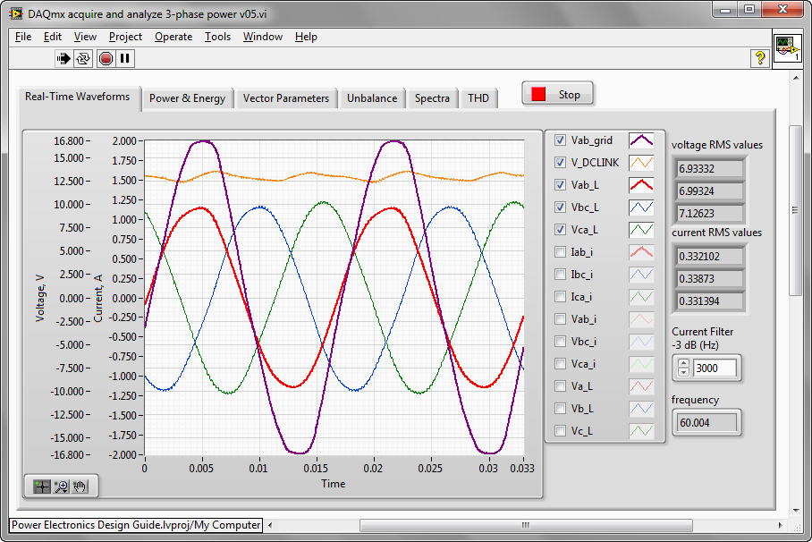
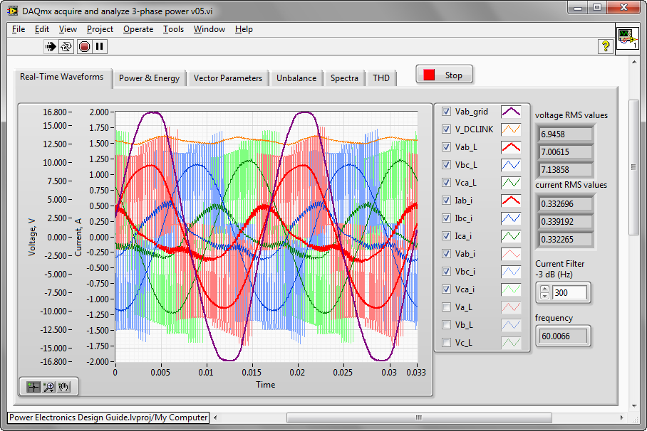
Below are screenshots from the 3-phase inverter control data acquisition application that show the fully instrumented 3-phase inverter. The single-phase grid voltage, filtered and unfiltered load voltages are measured, as well as the current in the 3-legs of the inverter and DC Link Voltage. Since a simple-low cost resistor shunt on the bottom switch of each inverter leg is used, the current signal must be filtered (current measurements are only valid when the lower switch is closed).

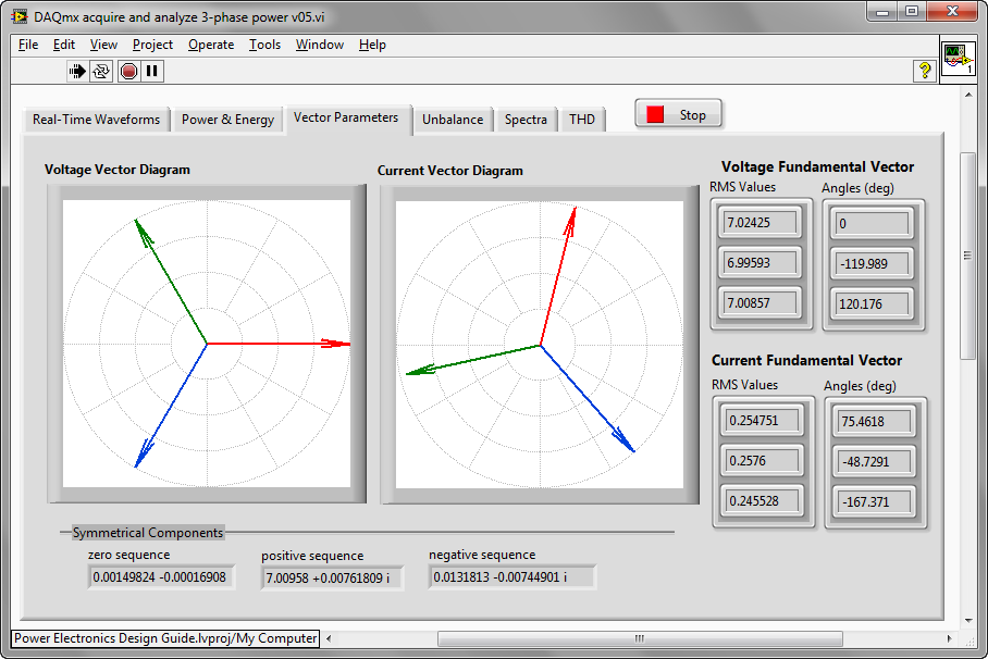
The phasor diagrams for voltage and current as well as the zero, positive and negative sequence values (a measure of imbalance) are shown. When this is running, the current vectors wobble around a bit as you'd expect. You can see that in the second video above. The phase of the first element of voltage fundamental vectors is always zero. The phases of other elements are relative to the phase of the first element.

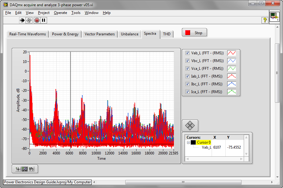
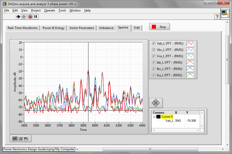
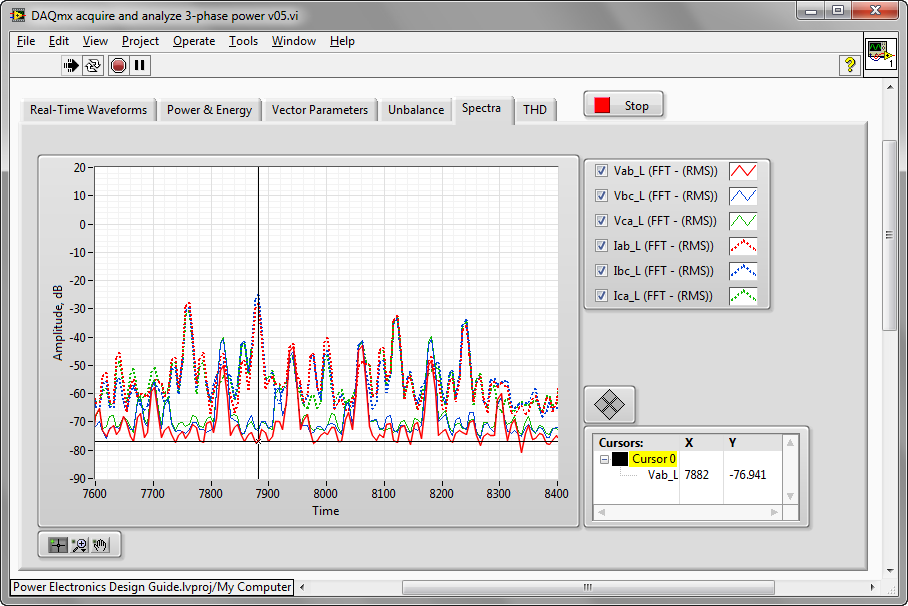
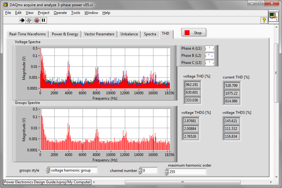
Performs FFT-based spectral measurements, in this case the averaged magnitude spectrum with amplitude in dB on the three-phase voltage and current waveforms. A Hanning window is applied and RMS averaging with exponential averaging over 10 cycles is used to enhance accuracy. The data is acquired from the ELVIS II+ DAQ board at 43.1965 kS/s, with each array containing 7.201 kS/ch.
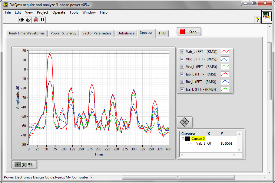
Here is a zoom on the 0 to 400 Hz range. You can see the fundamentals at the 60 Hz output frequency, f_o.
05-29-2012 12:30 PM
- Mark as New
- Bookmark
- Subscribe
- Mute
- Subscribe to RSS Feed
- Permalink
- Report to a Moderator
Two updates:
- To enable shorter order delivery time, Digikey in the U.S. will be increasing the stock of the STEVAL-IHM027V1 inverter boards (Digi-Key part number 497-10836-ND).
- Infinity Physics now offers inductors specially designed for the ELVIS trainer. The inductors provide 4.3 mH of inductance with low ESR on resistance (2.2 Ohm ESR) and instrumentation taps (link). Infinity Physics also offer custom winding and manufacturing services for magnetic components such as inductors and motor windings.
- A wiring schematics for the ELVIS protoboard jumper wires and ribbon cable connection is now available in PDF format and as PNG image (see below).
![ELVIS_PowerElectronics_Wiring_Schematic[1].png](http://forums.ni.com/legacyfs/online/34683_ELVIS_PowerElectronics_Wiring_Schematic[1].png)
06-19-2012 06:41 PM
- Mark as New
- Bookmark
- Subscribe
- Mute
- Subscribe to RSS Feed
- Permalink
- Report to a Moderator
Brian - this is incredible work. Very, very well done.
09-10-2012 06:32 PM
- Mark as New
- Bookmark
- Subscribe
- Mute
- Subscribe to RSS Feed
- Permalink
- Report to a Moderator
The link to FERRULE INS VNL AWG18 RD is incorrect (though the Digikey part number is correct).
Crimping stinks. 2x17 pin 0.1" pitch flat ribbon female/female header is... floppy drive cable! http://www.amazon.com/gp/product/B0002J2R6Y/ref=oh_details_o01_s00_i00
I purchased a different AC transformer, http://www.digikey.com/product-search/en/power-supplies-external-internal-off-board/wall-transformer... . Hopefully it works!
01-31-2014 07:22 AM
- Mark as New
- Bookmark
- Subscribe
- Mute
- Subscribe to RSS Feed
- Permalink
- Report to a Moderator
hello, where is the video ya?
Certified TestStand Developer (CTD)
Using LabVIEW 8.5.1 (2008) to LabVIEW 2021
01-31-2014 10:09 AM
- Mark as New
- Bookmark
- Subscribe
- Mute
- Subscribe to RSS Feed
- Permalink
- Report to a Moderator
I believe this could be the links...
Introduction to graphical system design methodology for power electronics
Part One: Introduction to Power Electronics Experiential Learning System based on NI ELVIS FPGA Board and 3-Phase IGBT Inverter
Part Two: Introduction to Power Electronics Experiential Learning System based on NI ELVIS FPGA Board and 3-Phase IGBT Inverter
Part Three: Introduction to Power Electronics Experiential Learning System based on NI ELVIS FPGA Board and 3-Phase IGBT Inverter
10-16-2017 07:40 PM
- Mark as New
- Bookmark
- Subscribe
- Mute
- Subscribe to RSS Feed
- Permalink
- Report to a Moderator
I am helping teach some high school kids electronics and I have acquired a NI Elvis II+ in a sale - but it did not have a power cord. Can someone please provide me with the pin out of the DIN-5 input power cable (which pins are GND, +5, +15 and -15 volts?) Amperages would be helpful as well if those are known.
Right now, I cannot use the unit at all...
Thanks!
- Mitch
10-19-2017 10:28 PM
- Mark as New
- Bookmark
- Subscribe
- Mute
- Subscribe to RSS Feed
- Permalink
- Report to a Moderator
Although it is not listed on the website, there is a shipping kit for the ELVIS II+ power supply. A sales representative should be able to create a quote for:
NI Part Number: 780382-01 NI ELVIS II/II+ Power Supply (power cord sold separately).
