- Subscribe to RSS Feed
- Mark Topic as New
- Mark Topic as Read
- Float this Topic for Current User
- Bookmark
- Subscribe
- Mute
- Printer Friendly Page
PXI 7841R Low frequency clock generation using FPGA Square wave generator
03-13-2018 08:56 AM
- Mark as New
- Bookmark
- Subscribe
- Mute
- Subscribe to RSS Feed
- Permalink
- Report to a Moderator
hello, im currently facing problems generating a square wave clock from the PXI-7841R, im using the FPGA Square wave generator and for some reason it seems to work on high frequencies, but on low frequencies the output of the square wave generator is always true
03-14-2018 03:41 PM
- Mark as New
- Bookmark
- Subscribe
- Mute
- Subscribe to RSS Feed
- Permalink
- Report to a Moderator
Hi peterRaafat,
At what frequencies does it stop working? What is "low"? And what frequencies does it work with? Are you specifying a duty cycle? Where are you changing the frequency?
Thanks,
Applications Engineering
National Instruments
03-15-2018 10:28 AM
- Mark as New
- Bookmark
- Subscribe
- Mute
- Subscribe to RSS Feed
- Permalink
- Report to a Moderator
thanks mr TimothyDug
Im not changing the duty cycle, it is kept at 50%. The frequencies i tried were 1 kHz 250Hz and 4 MHz
only the 4 MHz worked, actually the frequency that i need is 250 Hz.
03-15-2018 01:41 PM
- Mark as New
- Bookmark
- Subscribe
- Mute
- Subscribe to RSS Feed
- Permalink
- Report to a Moderator
Hey peterRaafat,
Thanks for the reply. I have some more questions to go over.
1. How are you changing the frequency? In the Express VI's settings?
2. Can you post your code?
3. Can you send a screenshot of the configuration of your Square Wave Express VI configuration?
4. What happens if you try to do a Sine Wave (in the same palette as Square Wave) at 250 Hz?
Thanks,
Applications Engineering
National Instruments
03-18-2018 09:24 AM
- Mark as New
- Bookmark
- Subscribe
- Mute
- Subscribe to RSS Feed
- Permalink
- Report to a Moderator
thanks mr TimothyDug
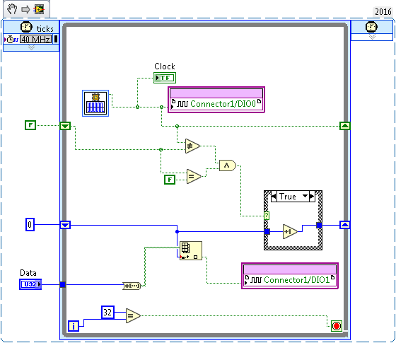
here is the code i am using
03-19-2018 09:51 AM
- Mark as New
- Bookmark
- Subscribe
- Mute
- Subscribe to RSS Feed
- Permalink
- Report to a Moderator
Hey peterRaafat,
Thanks for the reply! Where are you seeing the incorrect signal? I understand in the preview of the Express VI's settings, with a 40 MHz clock, you will not see the full period of a signal below 2 kHz in the preview window, but it should still output correctly.
Thanks,
Applications Engineering
National Instruments
03-20-2018 06:37 AM
- Mark as New
- Bookmark
- Subscribe
- Mute
- Subscribe to RSS Feed
- Permalink
- Report to a Moderator
i am using a logic analyzer to detect the output but still it doesn't read any output at low frequencies
03-20-2018 09:55 AM
- Mark as New
- Bookmark
- Subscribe
- Mute
- Subscribe to RSS Feed
- Permalink
- Report to a Moderator
Hey peterRaafat,
Thanks for the reply. Lets divide down the clock in the LabVIEW Project. You should have a 40 MHz clock in your project. Right click it and create a New FPGA Derived Clock. You will want it to be 5 MHz for the 250 Hz signal that you want.
Next, when you're configuring the Square Wave Generator, set the Frequency (top right box) to 250 Hz, as you wanted. Then, set the Execution Mode to Inside Single-Cycle Timed Loop. Next, you'll want to set the FPGA clock rate to 5 MHz. Finally, hit OK, and in your Timed Loop, double cdlick the top left box that says 40 MHz, and switch that to the newly created 5 MHz clock.
Run that, and you should be able to get the 250 Hz you want. Let me know how that works for you!
Thanks,
Applications Engineering
National Instruments

