- Subscribe to RSS Feed
- Mark Topic as New
- Mark Topic as Read
- Float this Topic for Current User
- Bookmark
- Subscribe
- Mute
- Printer Friendly Page
Engine Simulation Toolkit Feedback
01-20-2015 01:15 PM
- Mark as New
- Bookmark
- Subscribe
- Mute
- Subscribe to RSS Feed
- Permalink
- Report to a Moderator
Hi Suresh,
For questions other than Engine Sim Toolkit, you should contact your NI support representatives via ni.com/support
There is also a lot of great getting started material online at ni.com/veristand
To simply use the Engine Simulation Toolkit, follow these steps:
- Download the zip file attached to the page with 'built' in the name (at this time named: Engine Simulation Toolkit NIVS 2013 v1.3.1 Built.zip)
- Unzip the contents
- Close NI VeriStand
- Open the readme.rtf file and follow the instructions to install it
- Open NI VeriStand
- Open an existing or create a new project
- Open the system definition
- Right click custom devices and select National Instruments -> Engine Simulation Toolkit
- Use the browse button to select a bitfile either you have built yourself or someone has provided for you. You can select the example bitfile included in the zip file if you want to explore the functionality of the custom device while you wait for your personal bitfile.
To create a bitfile:
- Download the vip file attached to the page.
- Install it with VI Package Manager 2014 or later
- After installing, click 'examples' to navigate to the examples provided with the VI package
- Open the examples to see how the FPGA IP is put together
- Use the information from the example to create your own bitfile for your specific needs on your specific FPGA target
I really hope that helps. Have a great day!
01-23-2015 09:14 AM
- Mark as New
- Bookmark
- Subscribe
- Mute
- Subscribe to RSS Feed
- Permalink
- Report to a Moderator
This question relates to the Event Timing functions in the EST. The Crank and Cam signals seem to be working just fine, so I know that I've implemented at least some of this correctly, but at the moment I can't seem to capture either ignition or injection events from my ECM.
I have verified with my scope that the signals are being produced and should be present on the appropriate DI lines, but they never get captured. I've created two event windows, one for injection and one for ignition. I've added the measurements, selected the relevant windows, and set the polarities.
In my FPGA VI, I've wired the DI lines to the event inputs, all the <user name> fields have been updated and are consistent, and everything looks to be correct.
The I/O lines I'm using are the same that were used in the working LV/VS 2012 code, but that was based on the Engine Simulation Add-on, now replaced in the 2014 versions I'm using by the EST, obviously. The one difference, owing to the fact that I have two sets of ignition coils and only one pair works with the ECM I'm using, is that I switched two of the DI lines in the FPGA. Now, something that may or may not be relevant is that the DI lines are being read in a non-SCTL and written to a local variable. I inherited this architecture and at this point I don't want to make big changes and re-compile the FPGA VI yet again. So, all I did was create two new local variables and replace the existing ones in the ECU Event Timing SCTL. The DI lines that were in use are on an NI 9426, the new lines are on an NI 9423. No physical wiring has been changed, just the two local variables as described above.
One other thing that might be an issue is the FPGA config file. The two DI lines that I'm using now are referenced in the FPGA config file, they're the last two bits in the last DMA Read packet. I have no idea if this will cause a conflict, and it doesn't explain why I'm not seeing the injection events, because those DI lines aren't in the FPGA config file anywhere.
So, thoughts?
01-23-2015 10:16 AM
- Mark as New
- Bookmark
- Subscribe
- Mute
- Subscribe to RSS Feed
- Permalink
- Report to a Moderator
Hi ElectricWraith,
Glad you are having some success with the new stuff. According to everything you listed software wise, I don't see any problems.
I think the problem is your switching of 9426 to 9423. These modules are electrically different, as one is sourcing and one is sinking. Therefore if you're using the same ECU, I wouldn't expect changing the tester electronics to work.
You could test to see if the input boolean ever goes true by putting a simple counter on it. Count up when its true. If you see any counts you are reading pulses.
What are the electronics of your ECU? Are the injection lines low side or high side drivers? (usually they are low side). Are your ignition lines TTL for smart coils or something else?
01-23-2015 10:28 AM
- Mark as New
- Bookmark
- Subscribe
- Mute
- Subscribe to RSS Feed
- Permalink
- Report to a Moderator
Stephen,
Yep, I'm aware of the differences between the two modules, but they were already both wired in. The 9426 is wired up to a pair of smart coils and the 9423 to a pair of IGBT coils. The only thing that I switched was the local variable reads in the FPGA VI, swapping the existing pair for the smart coils with the pair for the IGBT coils. And recall, I made no changes at all regarding the DI lines for the injectors and I still don't see those events being captured.
Both injection and spark are low-side drive in my system, by the way.
I just keep getting the feeling that I'm missing something in the setup of the EST IP or the FPGA config, but nothing's jumping out at me. This is going to be something silly and simple, I guarantee it, I just can't see what it might be.
01-23-2015 10:38 AM
- Mark as New
- Bookmark
- Subscribe
- Mute
- Subscribe to RSS Feed
- Permalink
- Report to a Moderator
OK I understand better now thank you.
Can you send me your files? FPGA code project, NIVS sysdef, bitfile. I want to have a look.
Post here with the advanced editor button in top right
01-23-2015 11:20 AM
- Mark as New
- Bookmark
- Subscribe
- Mute
- Subscribe to RSS Feed
- Permalink
- Report to a Moderator
I can't tell if it's my machine, our IT policies, IE, or Chrome that's causing the problem here, but I keep getting errors trying to post in response to you with an archive file attached. The last time this happened to me, I ended up posting the same thing three times because the error was bogus. I'll PM you the password for the RAR file just in case it actually posted and I can't see it.
01-23-2015 01:10 PM
- Mark as New
- Bookmark
- Subscribe
- Mute
- Subscribe to RSS Feed
- Permalink
- Report to a Moderator
ElectricWraith,
I think I see the problem. The event inputs are not named correctly. Fixing these names should resolve some problems. Specifically, the indicators coming off event captures need more text.
If you look at the FPGA example that is included with the VI package, there is this
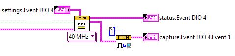
If you look at yours there is this:
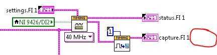
notice where I circled. You need a name of this event capture. So it should be something like capture.FI 1.Event 1
Because you can have multiple captures per event measurement, in the case of multi pulse injection. Since you only have one it might seem weird, but it still needs a name.
That causes it to show up wrong in system explorer:
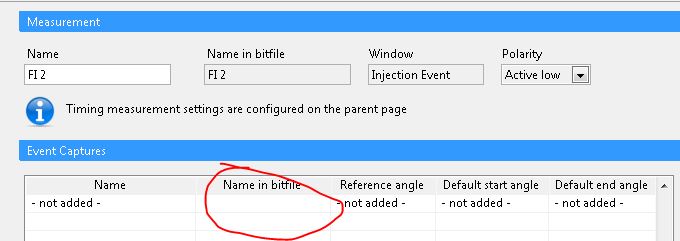
And therefore get added to the tree weirdly.
The Engine Sim Toolkit custom device should just not load these event captures with no names... as they don't work. So I'll file a bug to myself for that. Also, the 'event capture.vi' should have its output say capture.<measurement user name>.<capture user name>. I'll file an issue to myself for that too
Also, keep in mind the default for the new event measurement code is active low. The old AES was hard coded to active high. So if you need active high make sure to change that on the event timing page.
01-23-2015 04:04 PM
- Mark as New
- Bookmark
- Subscribe
- Mute
- Subscribe to RSS Feed
- Permalink
- Report to a Moderator
I never would have guessed that was the issue, but I knew it was going to be something simple. I even double-checked the names earlier today and saw that they were in line with the context help's description!
At any rate, I changed the names of the capture indicators to capture.FI 1.Front Injector, capture.FI 1.Rear Injector, capture.IC 1.Front Spark, and capture.IC 2.Rear Spark and re-compiled the FPGA. After reloading the path to the new bitfile, all of those event captures now show up in the System Explorer tree and have been added. I had to re-create my crank pattern and re-map a few things, but once I tried running the project I was able to see values for the Front Injector angle and duration, but that's it. I think there's either some configuration or mapping issues between my engine model and VS project, but I'm not sure at the moment.
I suspect, given the fact that the Front Injector capture appears to be working, that all of the captures should be correctly set up now. In other words, one works, they're all labeled the same in the FPGA, so it's likely not the FPGA code anymore. I'll keep picking away at it and let you know if I have any other questions.
Thanks a lot, you've been a HUGE help.
01-23-2015 04:11 PM
- Mark as New
- Bookmark
- Subscribe
- Mute
- Subscribe to RSS Feed
- Permalink
- Report to a Moderator
Awesome! Glad to hear that.
To debug I would start by widening the window. try 0-720 and -360 to 360. just make sure the pulse doesn't span the window begining/ending or it won't be counted. Actually, you can look at the 'status' channels to see if there are orphan edges or stuff like that.
also try changing active high/low.
01-28-2015 02:33 AM
- Mark as New
- Bookmark
- Subscribe
- Mute
- Subscribe to RSS Feed
- Permalink
- Report to a Moderator
Dear StephenB,
Thanks for guidance. I start to work with NI Veristand. But while i am
running the project it show error. The error is " no RT is connected with
the system". So please help me to recover tis problem
Thanks & regards,
suresh
