From Friday, April 19th (11:00 PM CDT) through Saturday, April 20th (2:00 PM CDT), 2024, ni.com will undergo system upgrades that may result in temporary service interruption.
We appreciate your patience as we improve our online experience.
From Friday, April 19th (11:00 PM CDT) through Saturday, April 20th (2:00 PM CDT), 2024, ni.com will undergo system upgrades that may result in temporary service interruption.
We appreciate your patience as we improve our online experience.
Purpose:
This lab demonstrates how to use the myDAQ or ELVIS II series to measure resistance (R), current (I), and voltage (V). LabVIEW and the NI ELVISmx virtual instruments are used in conjunction with the myDAQ or ELVIS II. The relationship between R, I, and V (or Ohm’s Law V = IR) is studied.
Background:
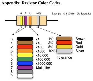
Resistors are the most common component found in all electrical and electronic circuits. Resistors are found in many shapes, sizes, and values. The most common shape is a two-lead cylinder component with leads coming out each end and color bands painted around the cylinder to indicate the nominal resistor value and its tolerance. Ohm’s law states that the voltage developed across a resistor is equal to the current flowing through the resistor times the value of the resistor or V = IR. Rearranging, the resistance is given by the ratio (V/I). Nominal resistance can be determined from the three colored bands closest together on the resistor, or read directly from a digital multimeter (DMM). The fourth band indicates your chosen resistor’s tolerance. It should have a tolerance less than 1% (brown), 2% (red), 5% (gold), or 10% (silver). Resistor tolerance is defined as the percentage difference between the measured resistance Rm and its nominal value Rn.
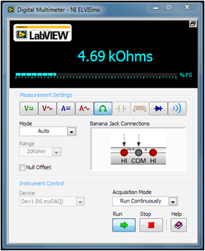
Figure 1: NI ELVISmx Digital Multimeter configured as an ohmmeter
Equpiment:
Prerequisite Reference Material:
Resistor Color Codes:
http://www.allaboutcircuits.com/vol_5/chpt_2/1.html
Using the myDAQ Digital Ohmmeter DMM (Ω😞
Using the myDAQ Digital Ammeter DMM (I):
Using the myDAQ Digital Voltmeter DMM (V):
Set Up Hardware:
Connect your myDAQ or ELVIS II board to the computer with the USB cable (supplied). Pick any three resistors and note the color bands. Read from the end band closest to the leads. The nominal resistance can be found using the color code in the Appendix at the end of this lab.
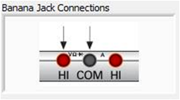
Figure 2: Banana jack connections for voltage or resistance measurements
Connect one of the resistors to your myDAQ or ELVIS using the supplied leads at the indicated inputs. Select the resistance function [Ω] button and change the mode (Specify Range) to (Auto). See Fig. 1. Press [Run] to view the resistance measurement on the display. Build the following circuit, which represents the voltage divider schematic that many sensor schematics follow:
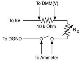
Figure 3: Voltage divider circuit
Now reconfigure the DMM front panel to read current by pressing the function ammeter [A-] button. Adjust the range to 20 mA.
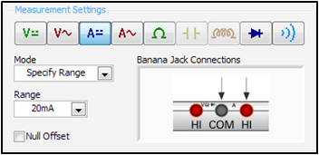
Figure 4: Measurement settings for DMM configured as an ammeter
Next connect leads from the myDAQ banana jack connections (Fig. 4) to your circuit (Fig. 3). Select the Run Continuously acquisition mode, and then press [Run] to make a measurement of the current flowing in your circuit:
I = ___________ mA
Remove the +5 V power lead. Set the myDAQ for DMM(V) for voltage measurement.
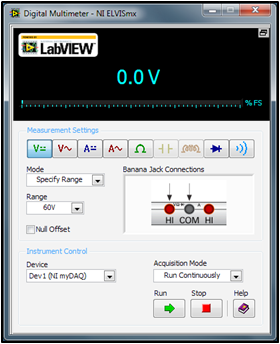
Figure 5: Measurement settings for DMM configured a voltmeter
Change the myDAQ banana jack leads to the voltage positions (Fig. 5). In the circuit of Fig. 3, replace the probe leads with wire as a short (bypass). Place the voltage probe leads across a 10 kΩ resistor. Reconnect the +5 V power lead and make a voltage reading by pressing [Run]:
V = _______________ volts
Software Instructions:
Thus far, we have shown how to make measurements for resistance, current, and voltage using the Virtual Instrument DMM. But there is more! You can embed your resistance meter inside a LabVIEW program and create a new instrument. Normally, you would read the color codes to select a particular resistor value; then you would verify your selection with the DMM(Ω). A LabVIEW program called Resistance to Colors.vi takes the reverse approach by telling you what the color code on the resistor should be based on an actual resistance measurement of a LabVIEW embedded ohmmeter. Load and view the front panel of Resistance to Colors.vi.

Figure 6: Measurement and colors of a nominal 47 kΩ resistor
Hook one of your resistors to the myDAQ or ELVIS banana jack leads, and click on [Run]. Try some other resistors.
How It Works:
The block diagram for this Resistance to Colors.vi is shown below:
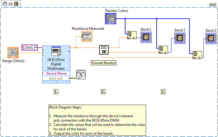
Figure 7: LabVIEW block diagram for program Resistance to Colors.vi
The resistance measurement is made within a Digital Multimeter VI. It is found in Functions/Programming/Measurement IO/NI ELVISmx/NI ELVISmx Digital Multimeter. The resistance measurement, a double precision number, is converted in the sub-VI called Format Resistor.vi into a color index number for the first two numbers of the resistance and the exponential power. The colors are stored in an array of LabVIEW color boxes labelled ‘ResistorColors’.
Example: R = 10000 Ω 1(Brown), 0(Black), and 3(Orange)
Hello there,
I'm very intersted in your tool and I would like to know more about how you choose the numbers for the limits and if possible more details at all for the Format Resistor part as not able to figure out some of the details by myself.
Thank you very much in advance,
Nik
