- Document History
- Subscribe to RSS Feed
- Mark as New
- Mark as Read
- Bookmark
- Subscribe
- Printer Friendly Page
- Report to a Moderator
- Subscribe to RSS Feed
- Mark as New
- Mark as Read
- Bookmark
- Subscribe
- Printer Friendly Page
- Report to a Moderator
Overview:
A thermistor is a two-wire device manufactured from a semiconductor material. It has a nonlinear response curve and a negative temperature coefficient. Thermistors make ideal sensors for measuring temperature over a wide dynamic range and are useful in temperature alarm circuits.
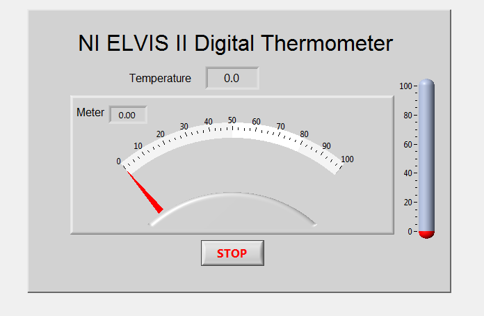
Figure 1: LabVIEW front panel for a digital thermometer
Purpose:
This lab introduces the NI ELVIS II variable power supply (VPS). You can use it with the workstation side panel controls or the virtual controls on your computer screen, or you can embed it inside a LabVIEW program. The VPS excites a 10 kΩ thermistor in a voltage divider circuit. The voltage measured across the thermistor is related to its resistance, which, in turn, is related to its temperature. This lab demonstrates how you can use LabVIEW controls and indicators together with NI ELVIS APIs to build a digital thermometer.
Equipment:
- 10 kΩ resistor R1, (brown, black, orange)
- 10 kΩ thermistor RT
- NI ELVIS II Series or myDAQ
*Note: If you are implementing this project with the myDAQ, instead of using a variable power supply (VPS), use the myDAQ's Analog Output to set the voltage.
Prerequisite Materials:
- Download LabVIEW:
- Thermistor Datasheet:
Set Up Hardware:
Measuring Resistor Values:
- Launch NI ELVIS II.
- Select digital multimeter (DMM) from the SFP strip of instruments.
- Click on the Ohm button.
- Connect the test leads to DMM(V,Ω, ►|) and (COM) side sockets.
- Measure the 10 kΩ resistor and then the thermistor .
- Fill in the following chart:
10 kΩ Resistor _________________ Ohms
Thermistor _________________ Ohms
7. With the thermistor still connected, place the thermistor between your finger tips to heat it up and watch the resistance changes. It is especially interesting to watch the changes on the display bar scale (%FS).
The fact that the resistance decreases with increasing temperature (negative temperature coefficient) is one of the key characteristics of a thermistor. Thermistors are manufactured from semiconductor material whose resistivity depends exponentially on ambient temperature and results in a nonlinear response. Compare the thermistor response with an RTD (100 Ω platinum resistance temperature device) shown in the following figure.
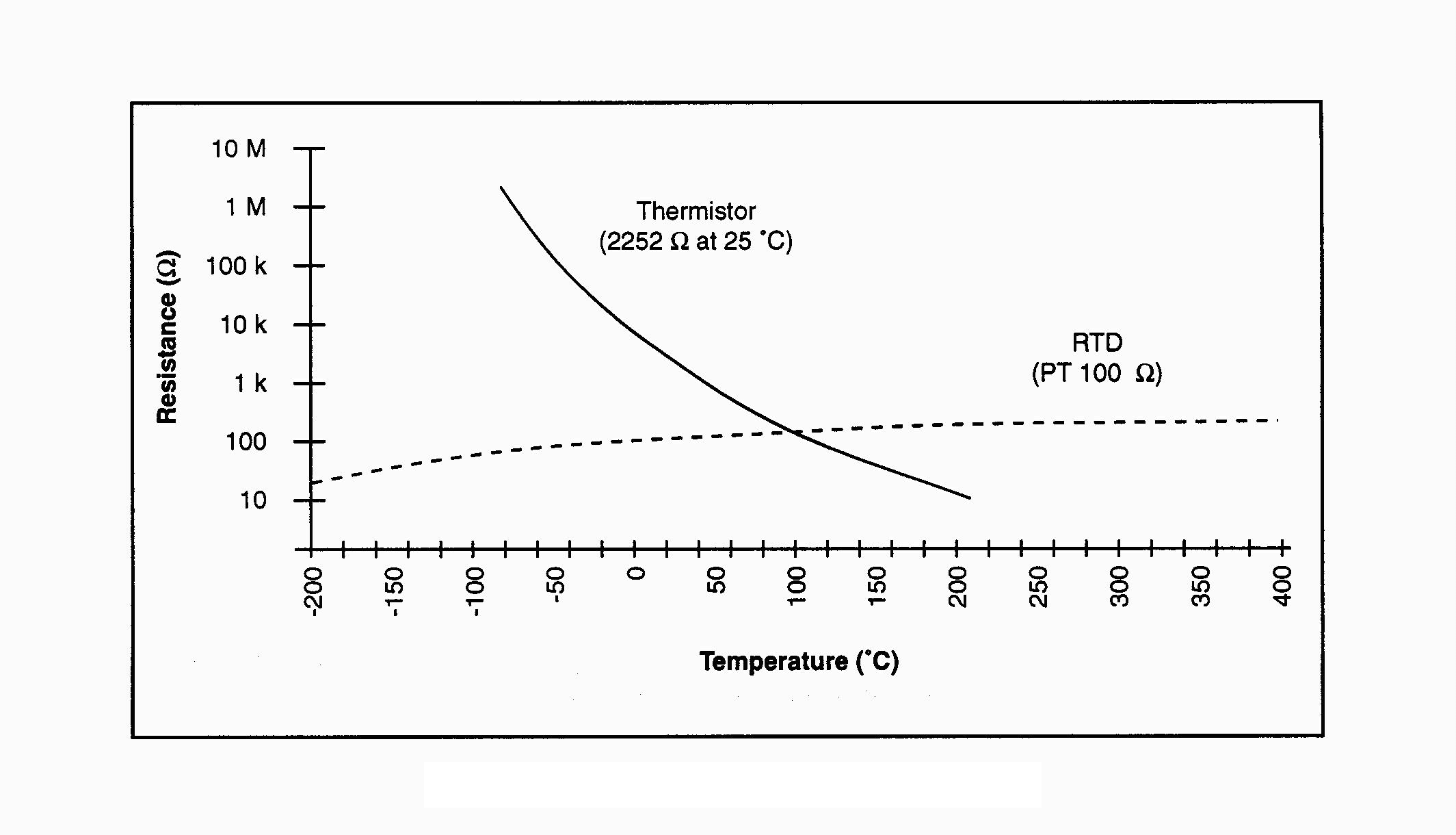
Figure 2: Resistance temperature curve of a thermistor and an RTD
Operating the Variable Power Supply
Complete the following steps to set a voltage level on one or both of the variable power supplies.
- From the strip menu of SFPs, select the [VPS] icon. There are two controllable power supplies with NI ELVIS II, 0 to -12 V and 0 to +12 V, each with a 500 ma current limit.
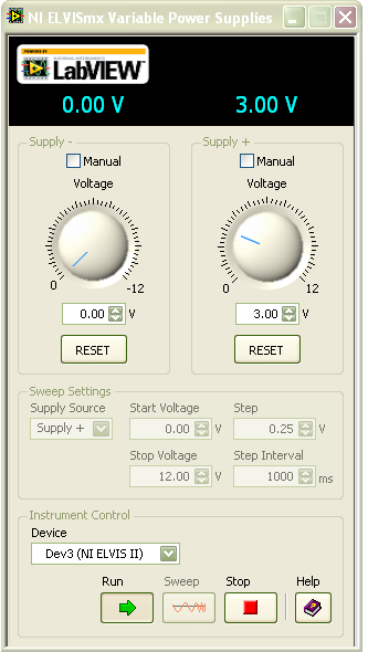
Figure 3: Virtual SFP for variable power supplies
In the default mode, you can control the VPS with the virtual panel shown above. Set the output voltage on the virtual knob and click on the [Run] box. The output voltage is shown (blue in color) in the display area above your chosen power supply. When you click on the stop button, the output voltage is reset to zero on the protoboard.
*Note: to sweep the output voltage through a range of voltages, make sure that you have clicked the [Stop] button. Select the Supply Source (+ or -), Start Voltage, Stop Voltage, Step Size, and Step Interval, and click on [Sweep].
For manual operation, click on the Manual box and use the knobs on the right side of the NI ELVIS II workstation to set the output voltages. To view the output voltage in the display area, click on the white box now appearing next to the LabVIEW label.
2. Connect the leads from the protoboard strip connector sockets labeled Variable Power Supplies [Supply +] and [Ground] to the DMM voltage inputs.
3. Select DMM
Rotate the virtual VPS control for Supply + and observe the voltage changes on the DMM
Note: You can use the [RESET] button to quickly reset the voltage back to zero.
4. Click on the Manual box to activate the real controls on the right side of the workstation. The virtual controls are grayed out. Observe that the green LED Manual Mode on the NI ELVIS II workstation is now lit.
5. Rotate the + voltage supply knob and observe the changes on the DMM.
*Note: VPS- works in a similar fashion except the output voltage is negative.
istor Circuit
A Thermistor Circuit
Complete the following steps to build and test the thermistor circuit.
1. On the workstation protoboard, build a voltage divider circuit with the 10 kΩ resistor and a thermistor. The input voltage is wired to [Supply +] and [Ground] sockets. The voltage across the thermistor goes to the DMM
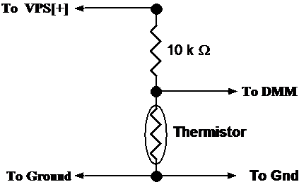
Figure 4: Temperature measuring circuit using a thermistor
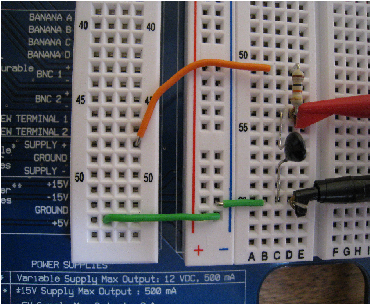
Figure 5: Real thermistor circuit on NI ELVIS protoboard
2. Make sure the Variable Power Supply voltage levels are set to zero. Apply power to the protoboard and observe the voltage levels on the DMM display. Increase the voltage from 0 to +5 V. The measured voltage across the thermistor, VT, should increase to about 2.5 V.
3. Reduce the power supply voltage to +3 V. This ensures that the self-heating (Joule heating) inside the thermistor does not affect the reading of the external temperature.
4. Heat the thermistor with your finger tips and watch the voltage decrease.
You can rearrange the voltage divider equation to calculate the thermistor resistance as follows:
RT = R1 * VT /(3 -VT)
At an ambient temperature of 25 °C, the thermistor resistance should be about 10 kΩ
With this equation, called a scaling function, you can convert the measured voltage into the thermistor resistance. You can easily measure VT with the NI ELVIS II DMM or within a LabVIEW program (VI).
Software Instructions:
In LabVIEW, the above scaling equation is coded as a subVI and looks like the following block diagram.
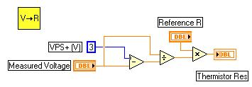
Figure 6: Block diagram for scaling function
The thermistor response curve demonstrates the relationship between device resistance and temperature. It is clear from this curve that a thermistor has the three following characteristics:
You can produce a calibration curve by fitting a mathematical equation to the response curve (see Appendix at the end of this chapter). LabVIEW has many mathematical tools to fit such a relationship. When you find the correct equation, you can calculate the temperature for any resistance within the calibrated region. The following calibration VI is typical for a thermistor and demonstrates how you can use the LabVIEW formula node to evaluate mathematical equations.
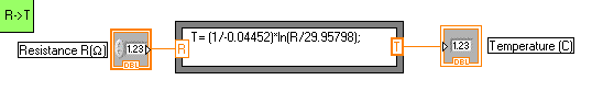
Figure 7: For this thermistor, the calibration equation is R = 29.95798 exp(-0.04452 T).
4: Building an NI ElVIS Digital Thermometer
Building an NI ElVIS Digital Thermometer
The digital thermometer program Digital Thermometer.vi activates the VPS to power up the thermistor circuit. It then reads the voltage across the thermistor, converts it into a temperature, and displays its value in a variety of formats on the front panel.
Measurement, scaling, calibration, and display occur in sequence within the while loop. VoltsIn.vi measures the thermistor voltage. Scaling.vi converts the measured voltage to resistance according to the scaling equation above. Convert R-T.vi uses a known calibration curve to convert the resistance into temperature. Finally, the temperature is displayed on the LabVIEW front panel as a number, meter reading, and thermometer display. The Wait function of 100 ms ensures that the voltage is sampled every one-tenth of a second.
All of these actions occur within the while loop until you click the [Stop] button on the front panel.
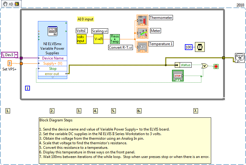
Figure 8: Block diagram for digital thermometer program
Thermistors, like resistors, create heat (Joule heating) as a current passes through them. For a thermistor that is trying to report the external temperature, this self-heating can be a problem. The trick is to minimize the current so that the temperature effects outside the thermistor dominate the self-heating. For your 10 k thermistor, a driving voltage of +3 V meets this requirement. With a LabVIEW Express VI, you can program the VPS on the NI ELVIS II workstation. The value 3 in the orange box sets a +3.0 V output on VPS+. One extra line, green in color, connected to the STOP icon ensures the VPS is reset to zero volts when the program ends.
Complete the following steps to open and view the components and code in the digital thermometer VI:
1. From the Hands-On NI ELVIS II library folder, open Digital Thermometer.vi.
2. Open the block diagram (Window»Show Block Diagram) and subVIs (double-click on the icons) to view the program flow and see how the subVIs and the Read and Convert functions are coded.
With the calibration curve for your thermistor, you can update the subVI (Convert R-T) with the proper equation and use it to achieve a functioning digital thermometer. If you want to write your own program, find the VPS API function in the Functions palette (Functions»Measurement I/O»NI-ELVISmx»NI-ELVISmx Variable Power Supplies).
Summary:
Congratulations! You have successfully acquired and manipulated data from a thermistor! Now that you understand how a thermistor works, you can incorporate it into a wide array of applications. From regulating the temperature of a room with a thermistor and air conditioner to monitoring the temperature of food in a cafeteria, thermistors are excellent tools for an engineer.
