- Document History
- Subscribe to RSS Feed
- Mark as New
- Mark as Read
- Bookmark
- Subscribe
- Printer Friendly Page
- Report to a Moderator
- Subscribe to RSS Feed
- Mark as New
- Mark as Read
- Bookmark
- Subscribe
- Printer Friendly Page
- Report to a Moderator
Overview:
Servo motors are used a large variety of applications, from small robotics to large-scale production lines. Infrared (IR) proximity sensors also have a wide scope of applications, such as PCs, cars, copiers, and TVs. This exercise will combine both servo motors and IR proximity sensors to produce a servo control system that may itself be used in many different applications.
Purpose:
This exercise demonstrates how to control a servo motor and take readings from an IR proximity sensor through the NI myDAQ or ELVIS II series. Basic concepts of the servo motor are introduced, and one can see how LabVIEW ties the input and output together.
Background:
Servo Motor Explanation
Typical servo motors differ from DC motors in that servo motors use a control signal to determine the output position of the servo shaft, while DC motors receive either a DC signal or pulse width modulated (PWM) signal to determine the output speed of the motor. The duty cycle, or ratio of high to low voltage, of a PWM signal drives the speed of the DC motor.
The control signal for a servo motor is very precise. Most servo motors require a set frequency of pulses (usually 50 Hz), and the duration of the control pulse, or “high” voltage pulse, is then varied to determine the shaft position. For this exercise, we will be using a special type of servo motor that varies the control pulse duration to control the speed of the motor rather than the position. The servo motor has multiple components, including a regular DC motor, a gear reduction system, a position sensor (typically a potentiometer), and a control circuit. The motor used in this exercise can be seen in Figure 1 below.
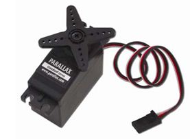
Figure 1: Parallax continuous rotation servo motor
IR Proximity Sensor Explanation
A detailed knowledge of IR sensors is not necessary for this exercise, although it is good to know that the sensor uses reflected infrared radiation to determine distances. Certain information is good to know about our specific sensor, however—most of which can be found on the datasheet in the Prerequisite Reference Material section. Take a look at Figure 2 below:
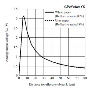
Figure 2: Proximity sensor response curve
The range of sensing is about 0-80 cm, although most of the useful linear information is found in the range of about 5-30 cm. For this reason, and simply to make our application more user-friendly, the LabVIEW VI that will be shown later in the discussion excludes large distance signals.
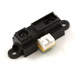
Figure 3: IR proximity sensor used in this exercise
Equipment:
- NI myDAQ or ELVIS II series
- NI Measurement and Automation Explorer
- NI LabVIEW
- Power transistor: TIP120 (x 2)
- Parallax continuous rotation servo motor (#900-00008)
- Sharp GP2Y0A21YKOF Sensor: www.sparkfun.com
- Recommended: 3-pin JST and JST connector (found at bottom of sensor’s webpage)
- 9 V battery
- Solderless Breadboard
Prerequisite Reference Materials:
Information on servomotors:
http://zone.ni.com/devzone/cda/ph/p/id/233
Parallax servo motor specifications:
http://www.parallax.com/Portals/0/Downloads/docs/prod/motors/900-00008-CRServo-v2.1.pdf
IR Proximity sensor specifications:
http://www.sparkfun.com/datasheets/Components/GP2Y0A21YK.pdf
Download LabVIEW:
How to use the NI ELVISmx Digital Multimeter DMM(V):
http://decibel.ni.com/content/docs/DOC-12937
How to use the NI ELVISmx Digital Signal Analyzer DSA:
http://zone.ni.com/devzone/cda/tut/p/id/11505
Set Up Hardware:
Connecting the Servo Motor
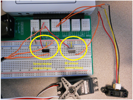
The first step is to connect the servo motor to the myDAQ or ELVIS II. The servo motor we are using requires about 5 VDC and 140 mA of current. The myDAQ can only supply 100 mA of current through its 5 V source, so we will use a battery and power transistor connected to the myDAQ to drive the servo motor. We will also connect the servo signal wire to the myDAQ, which will control the signal duration and frequency. Construct the schematic shown in Fig. 4 below on the breadboard. The real circuit can also be seen in the appendix.
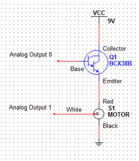
Figure 4: Multisim schematic of servo motor connection
The power supply and ground come strictly from the 9V battery, rather than the myDAQ. The wires labeled ‘Analog Output 0’ and ‘Analog Output 1’ correspond to the pins labeled ‘AO 0’ and ‘AO 1’ on the myDAQ. AO 0 is used to set the voltage into the motor, and AO 1 is used to output PWM signal to the motor. The red, white and black wires coming from the motor are the power, ground and control wires, respectively. The transistor in the schematic is an NPN Darlington transistor, which is equivalent to the TIP120. It shifts the voltage of the battery down to a voltage that is related to the output of AO0, while maintaining the high current provided by the battery.
Next, we need to set AO0 to a value that results in a transistor emitter voltage of about 5 V. Complete the following instructions to do so: Open Measurement and Automation Explorer --> Devices and Interfaces --> NI myDAQ “DevX” --> Test Panels --> Analog Output --> set Output Value to 7 (see Fig. 5 below). Use the NI ELVISmx Digital Multimeter (DMM) to measure the voltage between the transistor emitter and ground, which should be around 5 V. If not, adjust the Output Value for AO 0 or try a new battery. Place the servo motor off to the side of the breadboard to be used once the IR sensor is set up.

Figure 5: Screen shot of proper analog output voltage settings
Connecting the IR Proximity Sensor
The IR proximity sensor is connected to the myDAQ in much the same way as the servo motor. Our specific sensor operates at about 5 V, and so we can use the same TIP120, myDAQ and battery combination to power it. Construct the circuit shown in Fig. 6 on the breadboard. The real circuit can also be seen in the appendix.

Figure 6: Multisim schematic of IR sensor connection
The wires marked red, black and yellow are the sensor’s power, ground and signal wires, respectively. These wires may need to be wrapped around more sturdy wires in order for them to connect with the breadboard. AI 1+/- will be used to read the voltage from the sensor that indicates its proximity to an object. Place the IR sensor facing up on the surface you are working on, or tape/screw it to a perpendicular board/wall of some kind.
Software Instructions:
Open ‘distance servo control.vi’ and take a look at the Front Panel. The graph displays duty cycle variations over time (changes with hand position). All of the parameters are the same as those in ‘calibrate.vi,’ with the exception of ‘Duty Cycle,’ which is determined by hand position. These parameters, along with the data acquisition and output process, are explained in more detail in the steps provided on the block diagram of the program. You may also wish to check out the sub VI (hand in a box on the diagram) that acquires data from the IR sensor and converts it into a reasonable duty cycle. Simply double-click the sub VI box and read the notes on its block diagram.
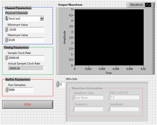
Figure 7: Front panel of 'calibrate.vi'

Figure 8: Block diagram of 'distance servo control.vi'
Note: The sub VI inside of distance servo control.vi uses an equation specific to the IR proximity sensor used in this exercise. If you are using a different IR sensor, the equation may need to be adjusted.
How It Works:
Calibrating the System
Our circuit is now ready to be tested in conjunction with a LabVIEW program that will take the input from the IR proximity sensor, convert it to a duty cycle, and output a signal with the specific duty cycle to the servo motor. This will allow us to control the speed of the motor with hand distance from the sensor. First, however, the motor must be calibrated to respond to the correct duty cycles. For our particular servo motor, a duty cycle of 7.5% results in a neutral motor position. In other words, if the output signal lasts for 1.5 ms every 20 ms, the motor will move neither clockwise nor counterclockwise.
Open ‘calibrate.vi’ and take a look at the Front Panel (or Fig. 7 above). There are multiple controls and dials. All of these should be set to the same values as those seen in Figure 7, and do not need to be altered if all of the equipment being used is the same as the equipment suggested by these instructions. If you are using a different servo motor, however, the amplitude, frequency, and other parameters may need to be adjusted. The Motor Speed dial may be adjusted to any desired setting as well. Hook your myDAQ or ELVIS II up to your computer, and make sure you are using the correct device port. Run the VI. A potentiometer rests in a small hole above the spot where the wires exit the motor. Using a small screwdriver, adjust this potentiometer until the servo motor is not moving in either direction, effectively calibrating the motor.
Testing the System
While we can be relatively certain that our program is generating the correct frequency output signal indirectly from the proper motor function, it is always nice to see direct proof. Open the NI ELVISmx Dynamic Signal Analyzer (DSA), which gives the power spectrum for a given input signal. Input the settings shown in Fig. 8 below, and run the ‘calibrate.vi’ program with the duty cycle at 7.5% and the DSA simultaneously. The fundamental frequency should read about 50 Hz—exactly what we expected our program to output to the motor. As the duty cycle is increased, the various fluctuations in the DSA power spectrum will change, but the fundamental frequency will remain 50 Hz.
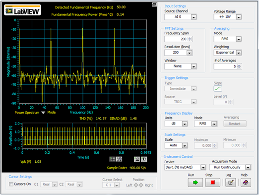
Figure 9: Power spectrum of the motor input signal provided by the NI Dynamic Signal Analyzer
Putting it all Together
Now we’re ready to run the motor with a program that adjusts the speed with hand position. Run 'distance servo control.vi'. Starting with your hand far away from the sensor, move it continuously closer and watch as the motor speed increases. Also, take note of the changes in the duty cycle on the Block Diagram, as the duty cycle should increase as your hand moves closer to the sensor. Adjust the knob titled ‘Motor Speed.’ This knob serves as an amplifier for the motor output signal, meaning if the knob is at a low setting, the motor have a lower duty cycle and thus will not move as quickly as it will at a higher setting and the same hand position. This concept is demonstrated in Figure 10 below.
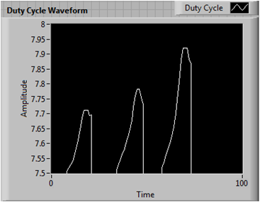
Figure 10: Duty cycle waveform showing increases with increasing motor speed
Each waveform represents a segment of time over which the hand was moved the same distance towards and away from the IR proximity sensor. The waveforms from left to right correspond to the Motor Speed knob adjusted to 0, 5 and 10, respectively
Summary:
Congratulations! You have successfully made a servo motor that is controlled by how far your hand is from an IR sensor. This application can be used to give automatic control to a robot that needs to sense a wall, among multiple other applications. We learned how to control a servo motor with PWM, how to perform a simple voltage conversion with a power transistor, and how to take measurements from a proximity IR sensor. We also demonstrated different I/O capabilities of the myDAQ and how it easily interfaces with LabVIEW. Hopefully this exercise has inspired you to create your own electronic application!
Webcasts, Tutorials, and Other How-To Resources
Learn About Relevant Training Options: Data Acquisition and Signal Conditioning
Appendix—pictures of motor and IR sensor connections

Applications Engineering
National Instruments
- Mark as Read
- Mark as New
- Bookmark
- Permalink
- Report to a Moderator
Has anyone else had errors when running the vi's? When running calibrate, I get a few errors. For example, -200220 and -200477.
PLEASE HELP MEEEEEEEEEEEEEE
- Mark as Read
- Mark as New
- Bookmark
- Permalink
- Report to a Moderator
Hey erip,
It's hard to tell what setting you had when you got these errors.
Error's like -200220 "Device identifier is invalid" usually indicates the Device selected, Physical Channel: "Dev1/ao1", on the front panel of the Calibration VI is invalid. Firstly, open Measurement Application Explorer (MAX) to verify the device you have connected is present on the system. Secondly, open Calibration.vi in LabVIEW, use the drop down to select/browse to the correct device you identified in MAX and then try running the VI again.
If this is not the issue, post your additional question here at the Academic Discussion Forum: http://forums.ni.com/t5/Academic-Hardware-Products-ELVIS/bd-p/10
- Mark as Read
- Mark as New
- Bookmark
- Permalink
- Report to a Moderator
Hey Andy,
Are you using NI ELVIS II as the controller for the servo? Can NI ELVIS II be used to control a brushless servo motor.
What driver are you using for the servo?
Can the control be done using MATLAB?
Thanks!
