- Document History
- Subscribe to RSS Feed
- Mark as New
- Mark as Read
- Bookmark
- Subscribe
- Printer Friendly Page
- Report to a Moderator
- Subscribe to RSS Feed
- Mark as New
- Mark as Read
- Bookmark
- Subscribe
- Printer Friendly Page
- Report to a Moderator
PID Motor Control
Overview:
This tutorial shows the characteristics of the proportional (P), the integral (I), and the derivative (D) controls, and how to use them to obtain a desired response with the NI myDAQ or NI ELVIS II series. This tutorial uses LabVIEW and the LabVIEW Control Design and Simulation Module with the PID Toolkit.
This tutorial is based in part on the Control Tutorials developed by Professor Dawn Tilbury of the Mechanical Engineering department at the University of Michigan and Professor Bill Messner of the Department of Mechanical Engineering at Carnegie Mellon University and were developed with their permission.
Purpose:
Learn concepts of proportional, integral, and derivative control, and use the myDAQ or ELVIS II to adjust the speed of a DC motor with PID control in LabVIEW.
Background:
The Three-Term Controller
Consider the following unity feedback system:
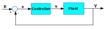
Figure 1: Unity Feedback System
Plant: A system to be controlled
Controller: Provides the excitation for the plant; Designed to control the overall system behavior
The transfer function of the PID controller looks like the following:
- Kp = Proportional gain
- Ki = Integral gain
- Kd = Derivative gain
First, let's take a look at how the PID controller works in a closed-loop system using the schematic shown above. The variable (e) represents the tracking error, the difference between the desired input value (R) and the actual output (Y). This error signal (e) will be sent to the PID controller, and the controller computes both the derivative and the integral of this error signal. The signal (u) just past the controller is now equal to the proportional gain (Kp) times the magnitude of the error plus the integral gain (Ki) times the integral of the error plus the derivative gain (Kd) times the derivative of the error.
This signal (u) will be sent to the plant, and the new output (Y) will be obtained. This new output (Y) will be sent back to the sensor again to find the new error signal (e). The controller takes this new error signal and computes its derivative and its integral again. This process goes on and on.
Characteristics of P, I, and D Controllers
A proportional controller (Kp) will have the effect of reducing the rise time and will reduce but never eliminate the steady-state error. An integral control (Ki) will have the effect of eliminating the steady-state error, but it may make the transient response worse. A derivative control (Kd) will have the effect of increasing the stability of the system, reducing the overshoot, and improving the transient response. Effects of each of controllers Kp, Kd, and Ki on a closed-loop system are summarized in the table shown below.
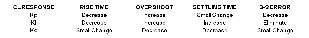
Note that these correlations may not be exactly accurate, because Kp, Ki, and Kd are dependent on each other. In fact, changing one of these variables can change the effect of the other two. For this reason, the table should only be used as a reference when you are determining the values for Ki, Kp and Kd.
Application:
The application demonstrated in this tutorial uses the myDAQ or ELVIS II to adjust the speed of a DC motor with PID control in LabVIEW. The tachometer (instrument measuring rotation speed of the motor) uses a Hall effect switch that turns on and off with the angular motion of a small magnet attached to the motor shaft. LabVIEW can then read a frequency from the switch, compare it to a desired frequency, and adjust the actual frequency with PID control to the desired frequency.
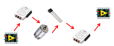
Figure 2: Control flow for our application
Equipment:
- NI myDAQ or NI ELVIS II
- NI LabVIEW
- Wire
- Protoboard
- DC motor
- TIP120 transistor
- 1 kΩ resistor
- Hall effect switch
- 9 V battery
- Small magnet
Set Up Hardware:
Wire the components to the myDAQ as shown below. If the ELVIS II is being used, all of the same ports can be used, with the exception of PFI9 in place of DI1. Both of these ports take in a digital frequency. The TIP120 is necessary to step up the current from the myDAQ or ELVIS II, as the analog outputs do not supply enough current to drive most DC motors. Make sure that the curved edge of the Hall effect sensor is directed towards the motor shaft, and that it is close enough to detect the magnet. The magnet may be hot glued on the shaft, or simply placed on, depending on its strength. It may be necessary to tape the motor to the board, depending on how much it moves.
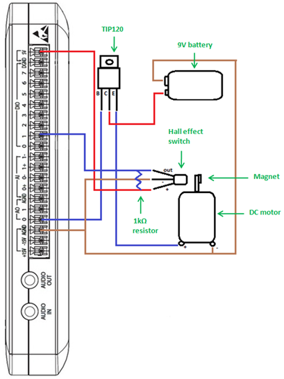
Figure 3: NI myDAQ Wiring Diagram
*Note: Red wires are directly attached to a power source, brown wires are directly attached to ground, and blue wires are directly attached to neither.
Software Instructions:
LabVIEW User Interface
The user interface we created allows the user to manually adjust the setpoint of the motor speed, the PID gains, and the output voltage range. It also displays the desired motor speed and the actual motor speed.

Figure 4: 'PID.vi' Front Panel
Coding Strategy
The basic coding strategy for our program is shown below. For a more detailed description, check out the block diagram of ‘pid.vi.’

Figure 5: 'PID.vi' Coding Diagram
The LabVIEW block diagram shown below looks very similar to the coding block diagram
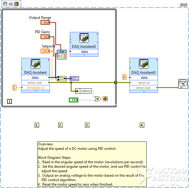
Figure 6: LabVIEW 2010 Block Diagram
How It Works:
Before running the PID control program, it is helpful to make sure that the Hall effect switch is working. To do so, hook up the output of the switch to AI0+ and AGND to AI0-. Run the oscilloscope from the NI ELVISmx Instrument Launcher, and move the small magnet close to and away from the sensor. Square wave pulses should be seen in the oscilloscope. Once proper operation of the Hall effect switch has been verified, and the circuit is set up to resemble Figure 4, we are ready it run the PID program. Open ‘pid.vi’ and click Run. The PID gains in place worked well for the motor we were testing, but yours may need adjustment. There are various methods of setting the PID gains, but one of the most common is simple trial and error. Adjust the setpoint motor speed, and observe the actual motor speed. Based on the effect of the PID gains on the system in Figure 2, adjust the gains to make the motor speed smoothly and quickly adjust to match the setpoint.
Tips and Tricks:
- While running the program, apply a force to the end of the motor shaft, slowing the motor speed. Watch as the speed automatically adjusts to remain at the setpoint speed.
- You can modify the VI to log the data to file using a ‘Write To Spreadsheet File.vi’ express VI if you wish to save the data. Be sure to place it in the loop and be sure to append new data to the spreadsheet file.
- Expand your application by integrating more functionality into the VI. Examples include automating the process of adjusting the PID gains for optimal motor speed transition, or using a servo motor with pulse-width modulation (PWM) instead of a DC motor with constant voltage.
Webcasts, Tutorials, and Other How-To Resources
Learn About Relevant Training Options: Data Acquisition and Signal Conditioning
Applications Engineering
National Instruments
- Mark as Read
- Mark as New
- Bookmark
- Permalink
- Report to a Moderator
Good day all,
I am a tyro in Labview> I would like to change the stiffness of a spring by running a dc motor to drive it thereby varying its length. This is simply an absorber. Please can anybody assist in this respect, dont even know where to start from on PIDController for Vibration absorbtion.
- Mark as Read
- Mark as New
- Bookmark
- Permalink
- Report to a Moderator
Hi,
I have a problem with my VI, when i run the VI this give me an error about a possible reason of timeout expired in the DAQ ASSISTANT (1) , and the motor is not runing, how can i fix this problem?
Regards
- Mark as Read
- Mark as New
- Bookmark
- Permalink
- Report to a Moderator
how do i incorcoporate the same(PID Control) using cRIO-9076 alongwith C series module NI-9516 for servomotor
- Mark as Read
- Mark as New
- Bookmark
- Permalink
- Report to a Moderator
Hi every body. I am doing dc motor control with PID controller with LABVIEW 2014. Please help us for we don't know more about LABVIEW. with thanks.
- Mark as Read
- Mark as New
- Bookmark
- Permalink
- Report to a Moderator
It's very useful for me learning PID in field of LabVIEW ,Thanks!
- Mark as Read
- Mark as New
- Bookmark
- Permalink
- Report to a Moderator
i have developed a vi for feedback control for motor.
when do it run program to count only rpm of motor via incremental encoder it does work well
when do i give setpoint analogue voltage output signal to vfd AI 0-10v it does work well.
but when i use PID for feedback as shown in attached file.The pid vi icon doesn't pass signal to analogue output daqass which in reply doesn't start motor.
anyone can help me in this regard or share his vi?
- Mark as Read
- Mark as New
- Bookmark
- Permalink
- Report to a Moderator
I have made pid for control dc motor speed with basic block diagram,when i am running its shows error with overshoot of 5v
I m just wondering, i have subtracted setpoint values minus my measured values coming from sensor, now where to connect my pid feed back node. If i connect feedback node to setpoint again its means i m subtracting twice
Please let me know if any one understands this problem
- Mark as Read
- Mark as New
- Bookmark
- Permalink
- Report to a Moderator
Thanks for the tutorial!
Now if I want to control the power supply in order to control the voltage output of my cartridge heater, how can I get P, I and D values? Thanks a lot!
