From 04:00 PM CDT – 08:00 PM CDT (09:00 PM UTC – 01:00 AM UTC) Tuesday, April 16, ni.com will undergo system upgrades that may result in temporary service interruption.
We appreciate your patience as we improve our online experience.
From 04:00 PM CDT – 08:00 PM CDT (09:00 PM UTC – 01:00 AM UTC) Tuesday, April 16, ni.com will undergo system upgrades that may result in temporary service interruption.
We appreciate your patience as we improve our online experience.
Overview:
DC motors are commonly used in applications ranging from robotics to medical devices. DC motors convert electrical power into mechanical power in a fairly simple manner. While the theory behind how an electric motor works is relatively straight forward, actually utilizing the motor in a circuit is a bit more nebulous. There are a number of ways to control the power and direction of a DC motor, and in this tutorial, you will create a motor driver using an H-bridge.

Figure 1: DC brush motor
Purpose:
This exercise demonstrates how to implement an H-bridge to control a DC motor using the NI myDAQ or ELVIS II series. Basic theory of how a DC motor operates will be presented along with how an H-bridge allows the user to programmatically control the direction and state of the motor.
Background:
DC Motor Explanation
There are two main parts of a DC motor: the stator, which is stationary and includes coils of wire called field coils, and the armature, which rotates around the stator. The armature also has coils of wire wrapped around it, and the ends of each wire coil terminate at one end of the armature. These points of termination are called commutator segments. The commutator is where brushes make electrical contact and supply the current needed to rotate the armature. To make this clearer, refer to Figure 2 below.
Figure 2: Magnetic diagram explaining the operation of a simple two-pole DC motor
In this simple two-pole motor, the stator is the coil of wire connected to the voltage supply on the left and will be referred to as the field coil. The bar magnet on the right represents the rotating armature. In part (a), the North pole of the armature repels the North pole of the field coil, which causes the armature to rotate toward the South pole of the field coil as shown in part (b). Before the armature can lock in place in the more attracted position, however, the polarity of the armature must be switched. Part (c) shows the armature as an electromagnet whose polarity is changed by reversing the direction of current flow through the armature. Commutator segments are provided for each terminal of the armature’s magnetic coil. To provide power to the armature, a stationary set of carbon brushes rides on the commutator segments to make contact with the rotating armature. When contact is made, current will flow through the armature.
Let’s walk through one rotation of this motor. First, DC voltage is applied to the field coils on the stator and to the brushes on the commutator segments. The brush connected to the positive voltage source causes the commutator segment it’s sitting on to be positive, as well. The same holds true for the negative brush. After voltage is applied, the armature will begin to rotate. When the armature gets to the point of greatest attraction (north poles nearing south poles), the negative brush touches the positive end of the armature coil and the positive brush touches the negative end of the armature coil. This action switches the direction of current flow through the armature, which subsequently switches the polarity of the armature coil so that the repelling and attracting continues. The polarity of the armature switches twice during each rotation since this is a simple two-pole motor. This will result in a rough, jerking motion that won’t provide much torque. Motors that are actually used in practice generally have many more field poles and armature poles to achieve greater torque and fluidity of motion.
H-bridge Explanation
An H-bridge is an excellent beginner’s DC motor driver circuit. It is composed of four bipolar transistors arranged in an “H” shape, which allows a user to electronically command the motor to move forward, reverse, brake, and coast. Figure 3 shows the schematic of an H-bridge made in Multisim. The four diodes are included to ensure that excess motor energy is dispersed when the motor is set to stop or coast in order to protect the H-bridge. Without diodes, a spike in motor voltage could damage transistors.
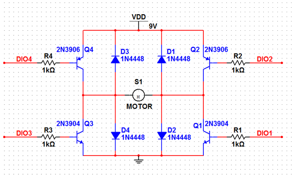
Figure 3: H-Bridge schematic designed in Multisim
Each of the transistors is connected to a separate Digital I/O pin on the myDAQ in order to control what state the motor is in. For example, when 5V is applied to R3 and R4 and when both R1 and R2 are grounded, current flows from R3 right through the motor and through R2 to ground. How does the motor change direction? When R1 and R2 are instead set to 5V and R3 and R4 are grounded, current flows in the opposite direction through the motor.
Equpiment:
Prerequisite Reference Material:
Introduction to DC motors:
http://zone.ni.com/devzone/cda/ph/p/id/52
Datasheet for the PPN7A12C1 DC Brush Motor:
http://www.nmbtc.com/pdf/motors/PPN7.pdf
Download LabVIEW:
Set Up Hardware:
Construct the circuit shown in Figure 3 above. The power rails should be connected to the terminals of a 9V battery while DIO1-4 should be connected to the corresponding digital IO pins of the myDAQ or ELVIS II board. The battery is used to provide enough current to the motor. The resultant physical circuit is shown in Figure 4.

Figure 4: Breadboard implementation of H-Bridge
Software Instructions:
In order to control the direction of the motor, we need to programmatically set specific pins to 5V and ground. In order to do this, open up “H Bridge Motor.vi”. As you can see on the front panel (Figure 5), there is a drop down menu called Select Command, four LEDs, a physical channel selector, and a Stop button

Figure 5: Front panel of H Bridge Motor.vi
Figure 6 displays the block diagram of “H Bridge Motor.vi” but more details about the functionality of the vi can be found on the block diagram itself.
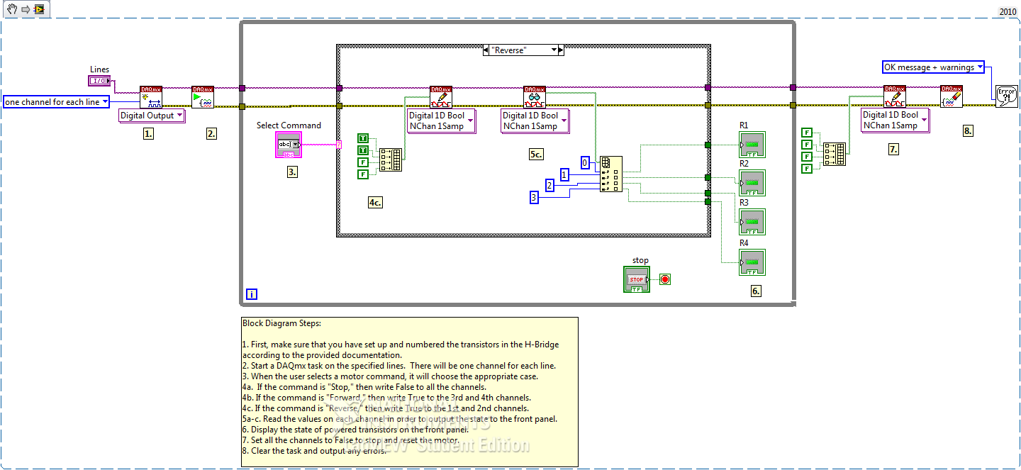
Figure 6: Block Diagram of H Bridge Motor.vi
How It Works:
Open Measurement and Automation Explorer. Under the Devices and Interfaces section, find the myDAQ or ELVIS II icon. Note what device number it has been assigned (“Dev1” etc). On the front panel of “H Bridge Motor.vi,” select lines 1-4 on your device. Once this is done, your vi is ready to run.
When you run this vi and select “Forward,” R3 and R4 will light up, indicating that power is currently being applied to those resistors. If you then select “Reverse,” R1 and R2 should instead light up. This gives you a visual representation of how current is flowing in your circuit.
To better visualize the change in motor direction, cut out a notch in a paper circle and punch a small hole in the center. Push the rod on the motor through the hole so that it fits tightly. Now, run the vi again and watch as the motor changes directions.
FYI D2 and D4 are drawn reversed in the schematic but not in the actual circuit picture. The Diodes should be reversed from shown in the schematic.
do we need to connect a di gnd for this circuit!!
Hello,
I'm trying to replicate this in Multisim. Where is the S1 Motor component shown in Figure 3 coming from in the MultiSim database?
I'm looking under the Electro_Mechanical Database using MultiSim 14.1, and it's not there.
Thanks
Dennis
