From Friday, April 19th (11:00 PM CDT) through Saturday, April 20th (2:00 PM CDT), 2024, ni.com will undergo system upgrades that may result in temporary service interruption.
We appreciate your patience as we improve our online experience.
From Friday, April 19th (11:00 PM CDT) through Saturday, April 20th (2:00 PM CDT), 2024, ni.com will undergo system upgrades that may result in temporary service interruption.
We appreciate your patience as we improve our online experience.
It is easy to read digital lines with software timing in LabVIEW, but this limits the refresh rate to the speed at which LabVIEW can update. To increase the read rate, you can use one of the NI ELVIS’ counters to clock the digital lines.
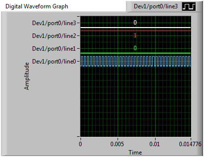
Figure 1- VI reading a 2.5kHz signal
This could be used to study the operation of a digital integrated circuit (IC), such as a 555 counter IC. LabVIEW is unable to update fast enough to allow the user to see the order in which each digital line changes. However, if the counters are used to clock the digital lines, very high sampling rates can be achieved, allowing the user to study the operation of the counter.
The NI ELVIS comes with everything needed for this demonstration. The only hardware setup that is necessary is connecting a digital waveform source to one of the first 4 digital lines. If an external digital waveform is available wire it to DIO 0, DIO 1, DIO 2, or DIO 3, found at the top right corner of the proto-board.

Figure 2- NI ELVIS II Proto-board
If an external digital waveform is not available, wire the function generator (FGEN) to one of the mentioned digital lines.
Start by either downloading the two attached VI’s or looking them up in the example finder. If you want to use the example finder, open a blank VI and click on Help>>Find Examples… at the top of the task bar. Next, go to the search tab and type in “Correlated Dig with Counter.” Open the VI with the searched name.
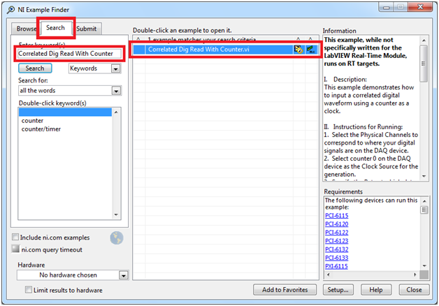
Figure 3- NI Example Finder
The VI is already configured to connect to “Dev1”. If your NI ELVIS is named something else, you can either rename your NI ELVIS in the Measurement and Automation Explorer (MAX) or re-link the VI to your NI ELVIS.
To re-link the VI to your NI ELVIS, click on drop-down bar labeled “Input Physical Channels,” and select “Browse…” at the top. Find your NI ELVIS device and, while holding shift, select lines 0 through 3 on port 0. Click “OK” while the lines are highlighted.
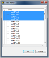
Figure 4- Selecting digital lines
Next, click on the drop-down bar labeled “Counter(s)” and select ctr0 for your NI ELVIS device.
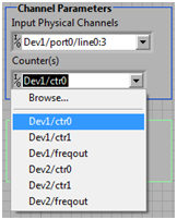
Figure 5- Selecting counter
Once you have the VI linked to your NI ELVIS, you can change the “Rate” to the desired clock speed. The VI is now ready to run, but if you do not have a digital waveform signal, not much will happen.
If you are using the NI ELVIS’ function generator as your waveform, follow the steps below to start the waveform.
1) Open the NI ELVISms Instrument Launcher by going to Start>> All Programs>> National Instruments>> NI ELVISmx Instrument Launcher for NI ELVIS and NI myDAQ>> NI ELVIS Instrument Launcher.
2) Click on the icon labeled “FGEN”
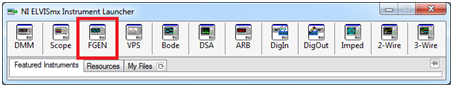
Figure 6- NI ELVISmx Instrument Launcher
3) Set the parameters to match the ones shown in the figure below and click “Run.”

Figure 7- Function Generator (FGEN)
Now, if you haven’t already, start the digital waveform reading VI. You should see whichever digital line you wired the FGEN to changing.
For information on how this VI works, refer to its block diagram. Each step has been documented and explained there.
Can you plese post those VI in LabVIEW 2009 version?
