- Subscribe to RSS Feed
- Mark Topic as New
- Mark Topic as Read
- Float this Topic for Current User
- Bookmark
- Subscribe
- Mute
- Printer Friendly Page
RTD simulation Help
11-14-2011 11:26 PM
- Mark as New
- Bookmark
- Subscribe
- Mute
- Subscribe to RSS Feed
- Permalink
- Report to a Moderator
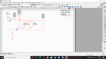
I am trying to use a VOLTAGE_CONTROLED_RESISTOR_VIRTUAL to simulate an RTD. From what I have read this is one way to simulate an RTD. I am using the voltage input as a simulation for temperature.
I want the value of my resistor to be 279.40 ohms @ 103.12 degreec C (or volts in this case).
I set the voltage supply to my VCR to 103.12V and the resistance value to 2.70946 ohms/volt
Am I missing something? What am I doing wrong?
Thank you,
Eric
11-16-2011 08:40 AM
- Mark as New
- Bookmark
- Subscribe
- Mute
- Subscribe to RSS Feed
- Permalink
- Report to a Moderator
Hi Eric,
I duplicated your circuit and there are two things you need to do get the right measurement:
- Reverse the polarity of the biasing battery, so the positive of the 103.12 battery to the positive of the voltage controlled resistor (VCR) and same for the negative end.
- When measuring the resistance of a VCR, it is better to measure the voltage accross and divide it by the current passing by because of the way the Ohmmeter device works (it adds a sample resistor in shunt and that will be affected by the controling voltage too). Another way is to run a DC operating point analysis and calculate this expression (V(1)-V(2))/I(R1).
I attached the design here.
Please let me know if you have other questions.
Mahmoud W
National Instruments
12-19-2020 03:31 PM
- Mark as New
- Bookmark
- Subscribe
- Mute
- Subscribe to RSS Feed
- Permalink
- Report to a Moderator
Greetings I am trying to simulate a 2 lead wire RTD using a VCR however i have issues with finding how to show how the resistance of the VCR changes with control voltage. My maximum control voltage is 105v which represents the temperature. Please help

