- Subscribe to RSS Feed
- Mark Topic as New
- Mark Topic as Read
- Float this Topic for Current User
- Bookmark
- Subscribe
- Mute
- Printer Friendly Page
PXI 6221 digital waveform output
12-19-2012 06:36 AM - edited 12-19-2012 06:36 AM
- Mark as New
- Bookmark
- Subscribe
- Mute
- Subscribe to RSS Feed
- Permalink
- Report to a Moderator
Im trying to output a digital waveform to one digital output of my PXI 6221 DAQ.
This is the block diagram :
This is the front panel
As you can see, the digital waveform outputs to the graph like it should.
But to DO 7, it seems to always writes the last bit of the binary string (in this case 0).
Also, I want this waveform to have a sample frequency using the internal counters.
How do I do this?
Thank you
12-19-2012 07:07 AM
- Mark as New
- Bookmark
- Subscribe
- Mute
- Subscribe to RSS Feed
- Permalink
- Report to a Moderator
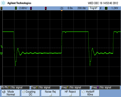
I've put DO7 on an osciloscope with triggering mode.
This is wat I got:
It seems to output at 1MHz. Its this frequency I want to change.
How do I do this?
12-19-2012 10:17 AM
- Mark as New
- Bookmark
- Subscribe
- Mute
- Subscribe to RSS Feed
- Permalink
- Report to a Moderator
You could change your sample rate. Use the DAQmx Timing VI.
There are only two ways to tell somebody thanks: Kudos and Marked Solutions
Unofficial Forum Rules and Guidelines
"Not that we are sufficient in ourselves to claim anything as coming from us, but our sufficiency is from God" - 2 Corinthians 3:5
12-19-2012 11:35 AM
- Mark as New
- Bookmark
- Subscribe
- Mute
- Subscribe to RSS Feed
- Permalink
- Report to a Moderator
M Series devices don't have a dedicated timing engine for digital I/O, so you'll need to route the clock from somewhere else. The most common solution is probably to use a counter, as in this example.
Best Regards,
12-20-2012 08:03 AM - edited 12-20-2012 08:11 AM
- Mark as New
- Bookmark
- Subscribe
- Mute
- Subscribe to RSS Feed
- Permalink
- Report to a Moderator
I'm using LV 7.1 and I can't find some VI's (device prefix).
Is there any other way to get a counter to be the source of the sample clock?
12-20-2012 09:43 AM
- Mark as New
- Bookmark
- Subscribe
- Mute
- Subscribe to RSS Feed
- Permalink
- Report to a Moderator
Hello kev91,
Here you can find the missing VI:
http://digital.ni.com/public.nsf/allkb/9D58153D1B5E5B66862574C8006A30FB?OpenDocument
Thierry C - CLA, CTA - Senior R&D Engineer (Former Support Engineer) - National Instruments
If someone helped you, let them know. Mark as solved and/or give a kudo. 😉
12-20-2012 11:02 AM
- Mark as New
- Bookmark
- Subscribe
- Mute
- Subscribe to RSS Feed
- Permalink
- Report to a Moderator
Ok thank you, I've managed to get it working thank you :).
Is it possible to use outputs synchronous?
This is what I already have, but it outputs an error:
12-20-2012 03:43 PM
- Mark as New
- Bookmark
- Subscribe
- Mute
- Subscribe to RSS Feed
- Permalink
- Report to a Moderator
The bottom of your screenshot is cut off, but it looks like you are trying to run two different tasks on the same device. You may only have 1 buffered digital output task per device (but that task may include multiple lines). Furthermore, only lines on port 0 of your M Series support buffered digital output (I can't see which lines you have selected from the screenshot).
Best Regards,
12-20-2012 05:19 PM
- Mark as New
- Bookmark
- Subscribe
- Mute
- Subscribe to RSS Feed
- Permalink
- Report to a Moderator
The bottom is basicly the,same as the middle one.
This is what I want to achieve:
I want one DO to output a clock signal for some time and another DO to go high every 200th clock signal. It needs to get high when the 200 clock signal just had its negative edge and needs to be low when the next clockpulse is high.
12-21-2012 02:21 AM
- Mark as New
- Bookmark
- Subscribe
- Mute
- Subscribe to RSS Feed
- Permalink
- Report to a Moderator
Hello Kev,
Is it possible to take multiple screenshots so that we can have an overview of what happens in the complete design?
Thierry C - CLA, CTA - Senior R&D Engineer (Former Support Engineer) - National Instruments
If someone helped you, let them know. Mark as solved and/or give a kudo. 😉


