- Subscribe to RSS Feed
- Mark Topic as New
- Mark Topic as Read
- Float this Topic for Current User
- Bookmark
- Subscribe
- Mute
- Printer Friendly Page
Strain gauge-based Load Cell
08-20-2017 07:10 AM
- Mark as New
- Bookmark
- Subscribe
- Mute
- Subscribe to RSS Feed
- Permalink
- Report to a Moderator
Hi guys,
I have a load cell (full bridge) which has the following characteristics:
Min. Input Signal = 0
Max. Input Signal = 2500 kN = 2500000 Newtons (Compression)
Excitation of 10V is provided internally by the module
Sensitivity at 10V = 20019.8 microvolts
Input impedance = 1050 ohms
Output impedance = 1050 ohms
Output without load = -137.367 microvolts
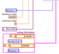
I use DAQmx to model the load cell. The load cell certificate doesn't provide any details regarding scaling that needs to be entered in LabVIEW. I have calculated the following:
Considering load cell supply is 10 Volts for max. signal of 2500 kN, and since sensitivity at 10V = 20.0198 mV, then
20.0198/10 = 2.00198 mV/V. So scaling information is:
0 mV/V - 0 Newtons
2.00198 mV/V - 2500000 Newtons
I am not sure If I need more values in the scaling information in DAQmx or these two values should simulate the load cell at its full capacity. Any thoughts should be much appreciated.
Thanks. S
08-20-2017 10:19 AM
- Mark as New
- Bookmark
- Subscribe
- Mute
- Subscribe to RSS Feed
- Permalink
- Report to a Moderator
When you use Scaling, you need to know several things. One is the "model" of your instrument -- is the Voltage Out a linear function of the Stimulus In? If so, then you can use linear scaling, which needs two parameters that I'll call "offset" and "gain". Offset is the voltage when the input signal is 0, while Gain is the change in voltage corresponding to a known change in input.
Assuming that (a) your Load Cell is linear (according to the manufacturer) and (b) the Offset is 0 (which you can test by taking a reading with a Load of 0), your calculations for determining Gain seem correct. But be careful -- if your device is designed to output 0-10V, and cannot (by design, for example) output -0.1V, then for all you know, an output of 0V with a load of 0 might be because the system wants to output -0.1V, but is "clipped" at 0V, a sign of a non-linearity in the Instrument and therefore a violation of the assumption for which you set up your scaling rules. An easy test for this is to take an "unloaded" reading, a "one-penny" reading (put a penny on the Load Cell), and a two-penny reading. Choose pennies with the same year, as the formulation can change. The voltage change from 0 to 1 penny should be exactly (!?!) the same as the difference between 1 and two pennies -- if there is a significant deviation, add a 5-penny value, plot the 0, 1, 2, and 5 penny values, and see if a straight line goes through the points, but hits the Y axis at a negative number.
Bob Schor
08-20-2017 03:49 PM
- Mark as New
- Bookmark
- Subscribe
- Mute
- Subscribe to RSS Feed
- Permalink
- Report to a Moderator
Thanks Bob.
The load cell is linear yes, however, if i use the calculated scale and there is an offset from the load cell, this offset can be deleted in the post-processing analysis of the recorded data right?
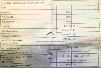
Here is the attached certificate of the sensor for your convenience:
Do I need to take anything else in consideration?
08-20-2017 06:21 PM
- Mark as New
- Bookmark
- Subscribe
- Mute
- Subscribe to RSS Feed
- Permalink
- Report to a Moderator
This sounds OK. However, I'm a scientist, by training, so I always believe in "doing an experiment" (like the Penny Weighing I mentioned) to demonstrate that things work as you think they should (or not).
Bob Schor


