- Subscribe to RSS Feed
- Mark Topic as New
- Mark Topic as Read
- Float this Topic for Current User
- Bookmark
- Subscribe
- Mute
- Printer Friendly Page
- « Previous
-
- 1
- 2
- Next »
Digital change at the same time?
10-21-2010 06:19 PM
- Mark as New
- Bookmark
- Subscribe
- Mute
- Subscribe to RSS Feed
- Permalink
- Report to a Moderator
Hi John,
I just realize that I misunderstood U32's meaning. It is the number of the digital channels's digital value right after the detection.
But the problem is still there. From the pictures shown below, from 3 to 0 and 0 to 3, both time intervals are around 3E-4. It should be one 3E-4 and the other 7E-4.
I modified the code and give counter a start time as the file attached, nothing changes. could you please help me with this?
Thanks
10-21-2010 06:39 PM - edited 10-21-2010 06:40 PM
- Mark as New
- Bookmark
- Subscribe
- Mute
- Subscribe to RSS Feed
- Permalink
- Report to a Moderator
Ah, you mean that it is not consistent in all runs. Once the run is executing, everything seems to be consistent.
I think you're on the right track by adding the Arm Start Trigger. However, the Counter and DI task are currently being started in the same frame of the sequence structure. If the DI task starts first, it could acquire samples before the counter task is ready to accept the Arm Start Trigger.
Try starting the counter task before starting the DI task.
Best Regards,
10-22-2010 03:59 PM
- Mark as New
- Bookmark
- Subscribe
- Mute
- Subscribe to RSS Feed
- Permalink
- Report to a Moderator
Hi John,
I modified it. Let counter get ready first then start DI task. But the problem is still there.
Another thindg I found is that. If I lower the input frequency to like 100Hz, no problem. If the input frequency is higher like 10K Hz, the error occures more frequently.
So is it possible that after the Arm Start Trigger signal send out, there is a delay before counter get the signal or a dealy between geting arm signal and actually starting counting edges?
Do you have other suggestions?
Thanks
10-25-2010 11:36 AM
- Mark as New
- Bookmark
- Subscribe
- Mute
- Subscribe to RSS Feed
- Permalink
- Report to a Moderator
Hi ossoo,
Since you are triggering and sampling off of the same signal, I think that you are correct about the problem--it is quite likely a race condition in hardware (sometimes the sample might be registered before the trigger, sometimes after).
Does your signal have to be free-running? Perhaps a solution would be to remove the Arm Start Trigger altogether and just make sure to not start outputting your signal until both the counter and the DIO tasks are started.
If this isn't an option, you might instead try to generate a re-triggerable single pulse based off of the change detection event to be used as a sample clock. The pulse would have a fixed initial delay so you could ensure to give enough time to arm the counter before the first sample is taken. The change detection event itself would be the arm start trigger for your edge count task, as well as the start trigger for your re-triggerable counter output task. The internal output of the 2nd counter would be the sample clock for your edge count task. You can set the initial delay in 12.5 ns increments (minimum of 25 ns).
Best Regards,
10-26-2010 02:37 PM
- Mark as New
- Bookmark
- Subscribe
- Mute
- Subscribe to RSS Feed
- Permalink
- Report to a Moderator
Hi John,
This works. I output the signal after both counter and DIO started. Everything is correct. Thanks a lot.
Another question:
How to convert the output to a digital waveform? Since the time for the digital data is random, I can not use the Build Digital Waveform function.
I can convert to xy graph, but it is not good enough, since I want the Y-axis show Channel Name, like Port0/Line8.
Could you help me with this? Thanks.
10-27-2010 09:09 AM
- Mark as New
- Bookmark
- Subscribe
- Mute
- Subscribe to RSS Feed
- Permalink
- Report to a Moderator
Hi ossoo,
In the Functions Palette » Programming » Waveform » Digital Waveform » Digital Conversion » Binary to Digital.vi, will that work for you? It converts 1D unsigned integers to a Digital Waveform.
National Instruments
Chief Applications Engineer
10-28-2010 05:18 PM
- Mark as New
- Bookmark
- Subscribe
- Mute
- Subscribe to RSS Feed
- Permalink
- Report to a Moderator
Hi Kyle,
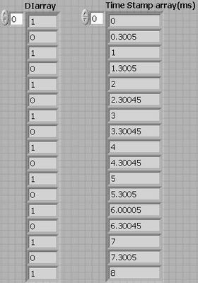
I have the digital data and timestamp array. Like the data below. Each DI data is corresponding to the time stamp value with the same index. How to covert to a digitall waveform? Thanks
10-29-2010 01:35 PM
- Mark as New
- Bookmark
- Subscribe
- Mute
- Subscribe to RSS Feed
- Permalink
- Report to a Moderator
Hey ossoo,
I put together this example that takes two 1D arrays, one with transition times and one with values, and it converts the waveform into a digital waveform to be used on an XY graph.
As far as using the built in VI's for the graphing, I couldn't find an easy way to do this correctly with the asynchronous timing.
National Instruments
Chief Applications Engineer
- « Previous
-
- 1
- 2
- Next »


