- Subscribe to RSS Feed
- Mark Topic as New
- Mark Topic as Read
- Float this Topic for Current User
- Bookmark
- Subscribe
- Mute
- Printer Friendly Page
Developing a line tracer robot using Starter Kit 1.0, and AUTOCAD
02-17-2013 02:35 PM
- Mark as New
- Bookmark
- Subscribe
- Mute
- Subscribe to RSS Feed
- Permalink
- Report to a Moderator
Hi guys how are you?, I'm a graduate from Mechatronics, and I am developing a project for my master, but so far I don't know if there is something alike or that can make this lots easier. I explain what I want to do:
- First, I have a drawing of a house or warehouse or some place made in AUTOCAD. Like the drawings architects use for designing houses.
- Then in that drawing we have in some layer lines that should be traced by our robot, could be straight lines, curves or even some shapes. I remark that in the drawing the lines to be traced and the plane of the place itself are in separated layers, so it will be easy to separate them after identifying them.
- For this I have the starter kit robot 1.0, and it should be able to recognize its environment with help of the drawing and the sensor (I'm thinking in buying a camera also), and then to trace the lines marked in the drawing (for this I will use a simple actuator with a marker attached to it, and in the program i will send a signal to the ouputs when it's time to trace).
Now, I see two big "stages/challenges" in this project:
1.- Move autocad drawings to labview to a program that recognizes them.
2.- Make the robot able to locate itself in the environment and recognize it, this in order to trace the lines according to the drawings.
I have read that it can be fast to use a program that converts the autocad file (dxf) into a file of x, y, z coordinates, and done this labview can recognize them.
But reading also about vision module I think about something like just loading the drawing file into labview and then labview generates it in 3D (with the help of some module), and then in some way just telling the robot to follow the lines marked in the drawing. Do you know how to do this?, or have something similar or that can help?
Also I think that of course using only the ultrasonic sensor I won't be able to recognize all the drawing and environment, instead I will buy an ip camera to monitor it and to give the robot its source of navigate, what do you think?
Thank you so much for yout attention and I hope you can help me.
Regards,
02-17-2013 11:05 PM
- Mark as New
- Bookmark
- Subscribe
- Mute
- Subscribe to RSS Feed
- Permalink
- Report to a Moderator
Hi, I am not quite undertand what you are going to do. Are you going to localize the robot's position by comparing the sensed data( camera, or unltrasonic sensor) and the AUTOCAD drawings of the house? What kinds of lines would you like to trace? some black lines on the ground or some visual features that is marked on the wall of the house?
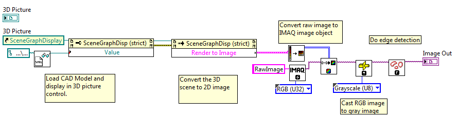
In LabVIEW, you can load a CAD file through several "3D Picture Control" APIs, but we supports only several CAD format like "STL", "WRL", etc. You need to convert your CAD file to the supported format by some 3rd part softwares. Once you load the file, you will get a 3D model and you can get the vertexs, colors of the CAD model through the propertys of the mesh refnum. You also can convert the 3D picture control view to a 2D image by the "Render to Image" method, and then you recognize some visual features using the vision module.
02-17-2013 11:36 PM
- Mark as New
- Bookmark
- Subscribe
- Mute
- Subscribe to RSS Feed
- Permalink
- Report to a Moderator
Hi my friend, yes I will try to localize the robot's position comparing the sensed data and the AUTOCAD drawings, unless there is something easier, I just want the lines to be traced well and not moved or bad (exactly as shown in the drawing). How I trace the lines doesn't really matter, what matters is them to be traced only, can be in any color or with any marker or pencil, for example if in the drawings is a star in the middle of the floor I have to trace that star, but can be with a marker or with a pen, I just need to identify after the robot passed over there. The house's walls can serve to locate the robot.
I will explore what you said about converting my CAD file into a STL, WRL, etc. file. Once I got them in that format, in the NI vision assistant is where I can put something like "load CAD file"?, or how can I get through this process of seeing on the screen the image?, it's just that I am not very familiarized with this module.
Thank you so much for your attention,I really appreciate your help,
Regards,
Sergio
02-18-2013 01:27 AM
- Mark as New
- Bookmark
- Subscribe
- Mute
- Subscribe to RSS Feed
- Permalink
- Report to a Moderator
Is this what you want? You can use "Render to Iamge" to get the 2D image of a 3D scene view and convert the image to a IMAQ image that "Vision" uses.
You can set the camera settings of the 3D picture control to get different view of the scene.

02-18-2013 10:19 PM
- Mark as New
- Bookmark
- Subscribe
- Mute
- Subscribe to RSS Feed
- Permalink
- Report to a Moderator
Yeah it's kind of what I want, let me check it and try it and i will tell you the results. I am buying the camera this week so I'll be able to install it on the robot and then try the 3D vision, I think I am buying the Axis 206 or M1011.
04-24-2014 01:47 PM
- Mark as New
- Bookmark
- Subscribe
- Mute
- Subscribe to RSS Feed
- Permalink
- Report to a Moderator
Hi Sergio, any experiences or antecedents of mounting an arm on the DaNI1?
Thank you.
manolo
