From Friday, April 19th (11:00 PM CDT) through Saturday, April 20th (2:00 PM CDT), 2024, ni.com will undergo system upgrades that may result in temporary service interruption.
We appreciate your patience as we improve our online experience.
From Friday, April 19th (11:00 PM CDT) through Saturday, April 20th (2:00 PM CDT), 2024, ni.com will undergo system upgrades that may result in temporary service interruption.
We appreciate your patience as we improve our online experience.
Country: Paraguay
Year Submitted: 2019
University: Universidad Católica "Nuestra Señora de la Asunción"
List of Team Members (with year of graduation):
- Micaela Carolina Jara Then Kathen (2019)
- Ariel David Bogado Arce (2019)
- Erid Eulogio Pacheco Viana (2019)
- Jesús Maria Franco Santacruz (2020)
Faculty Advisers: Prof. Gregorio Ariel Guerrero Moral
Main Contact Email Address: ariel.guerrero@uc.edu.py
Title: Development of an autonomous vehicle at a 1:8 scale
Description:
The challenge of the Robocar Race 2018 competition held in San Paulo-Brazil is to design an autonomous scale vehicle that can compete in 2023 against a radio-controlled car piloted by a man. Our team of students of the Universidad Católica Nuestra Señora de la Asunción” accepted the challenge and presented a solution based on inertial navigation using the NI myRIO and LabVIEW, being the first students of Paraguay to accept the challenge of building an autonomous car.
Products: NI myRIO 1900 and LabVIEW 2017.
The Challenge:
Brazilian branch of National Instruments challenged LabVIEW Student Ambassadors (LSAs) to design and build an autonomous scale vehicle to compete at the Robocar Race, in return, they would give them a NI myRIO controller. Our ambassador for PTI-UCA accepted the challenge and assembled the first team from Paraguay to develop an autonomous scaled vehicle. Our goal was to win the competition that consisted in running the track in the shortest time. We entered the race with our car called Aguara’i (little fox in Guarani), a Radio Controlled RC car that we modified to be autonomous. Although we finished in 4th place, our work inspired a lot of engineering students from our country to take part of this exciting and promising field.

The Solution:
Project Overview - The resulting performance of Aguara'i
System Configuration
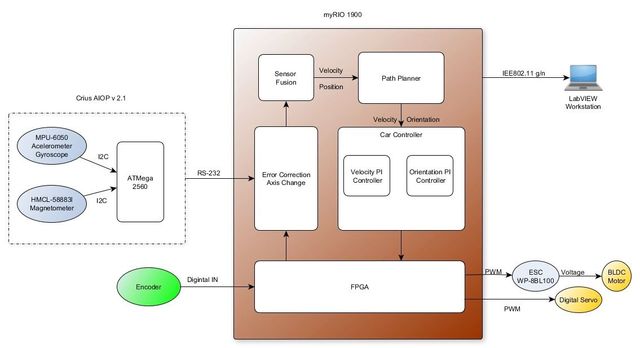
Autonomous Vehicle at 1: 8 scale: Modified chassis of a miniaturized electric RC car in which a myRIO 1900 is adapted as well as the sensors and actuators required for inertial navigation (IMU). In this platform the algorithms that allow determining the position and orientation information based on the sensors will be executed. It will also allow the acquisition of data from the sensors, execute the selected navigation algorithm and determine the control signals to the actuators.
Base Station: For configuration of the navigation parameters (waypoints) and visualization of the status of the sensors. Human-machine interface with LabVIEW.

Using LabVIEW and myRIO
The first step is to acquire the signals of the sensors. The encoder was connected to one of the FPGA’s (Field-Programmable Gate Array) inputs, and the IMU sensors was connected through a serial connection from an arduino microcontroller (ATMega2560) to the myRIO CPU.
In order to control the speed and direction of the car, we made use of the parallelism of the loops in the FPGA, these PWMs (Pulse Width Modulation) values to control the direction and the speed came from constantly updated values in the myRIO. To communicate this data from the RT-target to FPGA-target we use global variables, since we needed that several processes running in parallel in labview, can communicate their data and in this way obtain the processing and control of the state variables of the car in real time.
Next, the configuration of the system can be seen in Figure 1.

Sensor Fusion
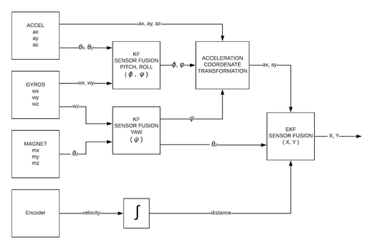
Sensor signals were used to improve and correct the position measurement of the 4-wheel autonomous vehicle to obtain a more reliable position estimate. From this, we calculated the estimation of the position and reduced the systematic and non-systematic errors during the tests and we succeeded in estimating the deviation of the turn bias. The basic tool here is a Kalman filter.

As shown in figure 2; Initially, a linear Kalman filter (KF) is used to merge the data of the accelerometer and the gyroscope, with this we obtain the pitch (φ) and roll (φ) angles, the yaw angle (ψ) is obtained from the fusion of the gyroscope with the magnetometer, also through a linear Kalman filter (KF).

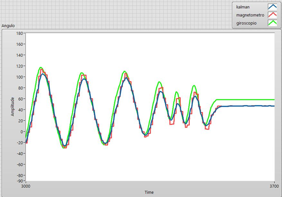
In Figure 3, the result of the fusion of the gyroscope and the magnetometer is shown. In it, the magnetometer does not have good response at high frequencies, however, at low frequency, the response is good. On the other hand, the behavior of the gyroscope curve is smooth, but the cumulative error increases and there is no way to correct it without performing the fusion of the sensors.
Finally, the encoder is added to the system, in order to have a better estimate of the distance traveled, an extended Kalman filter (EKF) is used, considering the non-linearity of the estimation by means of the odometry model.
This model is subject to cumulative errors that increase with time, because there is no external reference. These errors can be minimized by integrating a GPS (Global Position Systems) into the system, but this is beyond the scope of this work.
Path Planner
This module is responsible for taking the autonomous vehicle from an initial position to a final, following a trajectory. The algorithm used is the so-called pure pursuit algorithm. For practical purposes, the implementation of "Team 1712" has been used and modified according to the requirement.
With this algorithm it is possible to determine the target speed of the autonomous vehicle depending on the curvature of the segment of the trajectory in which the autonomous vehicle is located, as well as to establish the direction to which it should go knowing its current position and a target point called "Look Ahead Point".
To obtain greater precision in the calculation of the speed and curvature, points were injected into the original trajectory obtaining in this way closer points, to then passing through a smoothing stage and achieve continuity in the path.

The Conclusion:
If it wasn't for the NI platform,which made us achieve a very high level of development without entering into hardware programming and allowed us to make use of modularity even using third-party code, we wouldn’t have been able to develop the car in time for the competition.
This project was not carried out only by five people, this project involved the entire university community, students of electromechanical engineering, architecture and teachers of the university. In the aguara'i, the effort of each one of them, colleagues who worked with the members of the team during the morning, afternoon and night is put. This experience not only brought intellectual growth but also growth in teamwork. We learned that there are always people willing to help for the simple fact of being necessary. With the project it was possible to inspire the students of the inferior courses of the career and even to high school students , in the exciting area of the autonomous cars.
The Technical Description Paper (TDP), presented in Robocar Race 2018 competition, was selected, along with two others TDP, to be published in a journal of São Paulo, Journal of Production and Automation, besides, the paper achieved the first place in the Research Day organized by the Center for Research in Sciences, Technology and Advanced Innovation
(CICTIA) belonging to the institution. This project allowed to start a new line of research.
Time to Build:
This project was carried out in two months.The period in which it was made is September 2018 - October 2018