- Document History
- Subscribe to RSS Feed
- Mark as New
- Mark as Read
- Bookmark
- Subscribe
- Printer Friendly Page
- Report to a Moderator
- Subscribe to RSS Feed
- Mark as New
- Mark as Read
- Bookmark
- Subscribe
- Printer Friendly Page
- Report to a Moderator
Contact Information:
Country: Brazil
Year Submitted: 2019
University: Federal Institute of São Paulo (IFSP)
List of Team Members (with year of graduation):
Henrique Kubinhetz M. Ramos, 2018
Mariana Roskosz Gonzalez, 2018
Faculty Advisers:
M.S. David Rodrigo Gonçalves Ribeiro
Dr. Alexandre Brincalepe Campo
Main Contact Email Address:
rickubinhetz@gmail.com
marirsg59@gmail.com
Project Information:
Title:
A Portable Solution for Testing Aeronautical Jet Engines
Description:
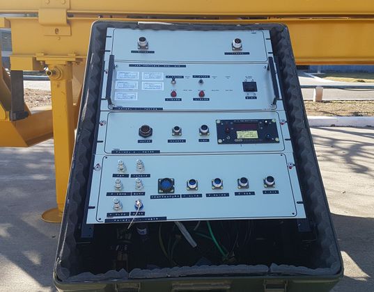
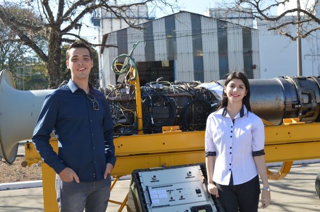
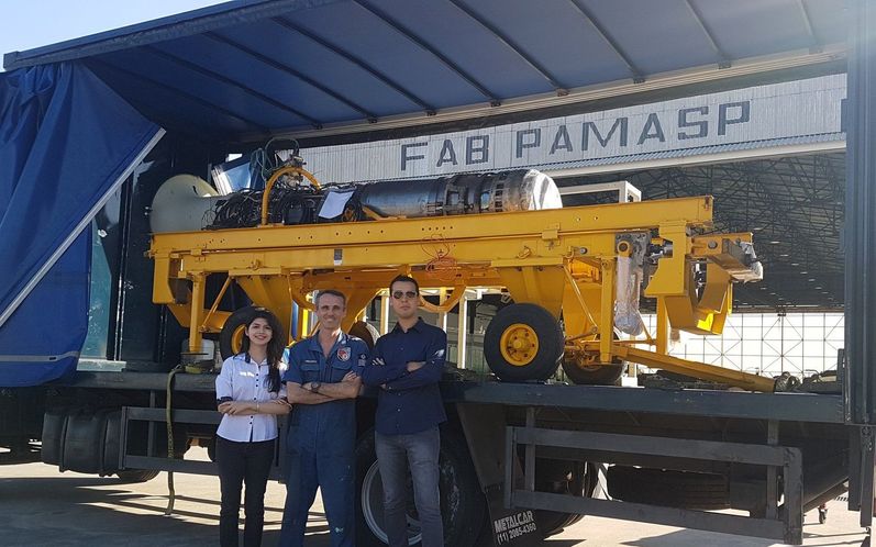
This work details a portable solution for a turbojet engines test system employed on the revision of military propellants in Brazilian Air Force aircraft. This project was necessary since engines of strategically located bases depended on a single maintenance facility, creating a logistical bottleneck. As a result, this is the situation where a portable system becomes a viable and relevant solution. Its structure contains all acquisition, processing, operation and logging functions in the same place, which is small and lightweight enough to be used in field-testing operations. The equipment inside it consists of a PC that serves as a human-machine interface, connected to a pair of devices that rely on a real-time controller and FPGA technology. It also brought optimization in productivity, shortened testing time and enabled significant fuel economy, which means lower maintenance costs.
Products:
Software:
LabVIEW 2017 Professional with FPGA and Real-Time add-ons.
Hardware:
CompactRIO 9031 controller with the following data acquisition modules:
- NI 9234, fuel flow and vibration are measured by this module;
- NI 9222 with the function of being a reserve module for future variables;
- NI 9229, responsible for RPM and Nozzle.
CompactRIO 9144 Expansion modules:
- NI 9222, IGV (Inlet Guide Vane) and Throttle;
- NI 9237, reads the CDP, barometric, fuel and oil pressures;
- NI 9237, SUMP and TANK.
- NI 9237, the data of the left and right load cells are obtained;
- NI 9213 module is responsible for the input of several thermocouples, six J-type and two K-type thermocouples were used for necessary assessments.
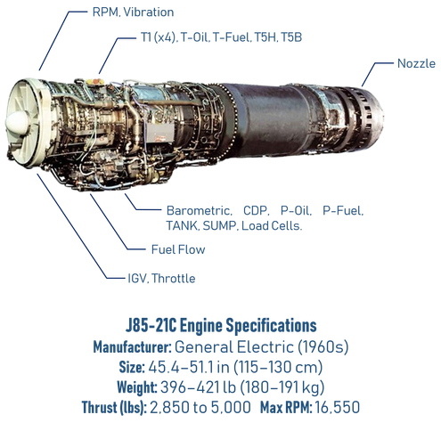
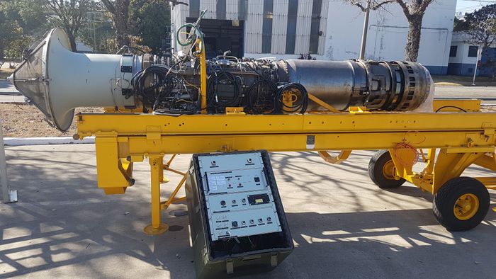
The figure below shows the employed propellant in higher detail. The General Electric J85-21C turbojet engine.
The Challenge:
This project has the following general requisites. It needs to have flexibility, the ability of making changes according to demands not yet foreseen. Scalability, so we can easily replicate the project and add new functionalities in both hardware and software. Determinism and Robustness are related to the critical nature of the task, where we need a high degree of confidence and safety in the operation.
The correlation test was a huge challenge and one of the biggest benefits brought by the portable system was the possibility of performing a more efficient correlation exercise, which brought an economy so big that it already paid for the project. The correlation exercise is something that must be performed every 2 years to properly calibrate the static closed test cell, taking into consideration the limitations on airflow. To calculate these compensation (or correlation) factors, the same engine must be measured in an open environment, which was impossible without a portable system. This forced the importation of equipment and professionals every two years, which wasn’t cheap. Now, this project grants autonomy to the Brazilian air force and will result in a great economy from now on.
After seeing the work done and the success obtained, more employees started to realize the importance and benefits of keeping the other test systems modernized. Changing the stagnated local culture of the airbase was a difficult task that also needed to be worked with. As a result, new projects began to be done. Consequently, an innovation and research environment was implemented inside the airbase.
The Solution:
The proposed structure consists of a PC (also called Host), which is the Human-Machine Interface (HMI), and two compactRIO that are connected through EtherCAT and Ethernet protocols. The first one has in its internal structure an FPGA and Real Time controller. These chassis are finally connected with the engine.
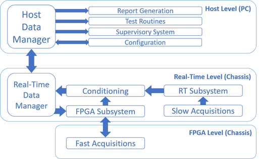
The project software is responsible for acquisition and conditioning as well as report generation. The algorithm has three levels: the FPGA, Real-Time and Host Level. They acquire variables divided into fast and slow categories. Fast variables are those that require signal recovery to better understand its behavior, such as Vibration, RPM and Oil Flow. They need to be acquired at a faster rate so that the signal of these variable could be recovered, and the frequency extracted for the necessary calculation and conversion to an engineering variable. On the other hand, slow ones don’t need such high acquisition rates, where only the last value provides satisfactory information for example temperatures and pressures.
The FPGA Level acquires the fast variables whereas the Real Time Level acquires the slow variables, treats and conditions these values and sends them upwards to the Host, where the user has the following options in a user-friendly interface: report generation, test routines, supervisory system and configuration. The following figure was taken from the article published about this project and illustrates how the program structure was organized.
Regarding the FPGA algorithm, there are three acquisition VIs, each referring to a module, and a management VI, which performs communication with the controller in real time. The blocks can individually handle configuration, data acquisition, queuing, safe shutdown and error handling operations. Each and every module has a state-machine structure as well as the Top-Level Master, so there is a lot of robustness and determinism in the code. The operation is independent and controllable, with redundancy structures that allow the code to regenerate after the data buffer overflow. The next figure was also taken from the same source.
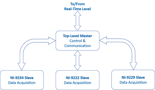
In case that one or more modules must to be added in this structure, it is perfectly possible to do so without the need to change it significantly, with great possibilities of reusing the code already built, which attests to the characteristics of flexibility and scalability required by the application.
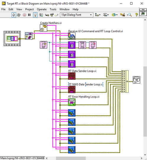
The Real-Time block has a slightly different structure: a queue-based state machine architecture. As a matter of fact, it is the system’s backbone, as it is responsible for the reception of all data, for the maintenance of the modules, for the conditioning of the signals and for the transmission of information appropriately structured for the human-machine interface. Each module’s code runs individually and can be controlled by the user. Due to the independent buffers there is no loss of data, as it is accessible both from the man-machine interface and from the state machines themselves, able to decide alone at certain times and write in their respective queues what the next step is. The Real-Time procedures can be seen in the next figure.
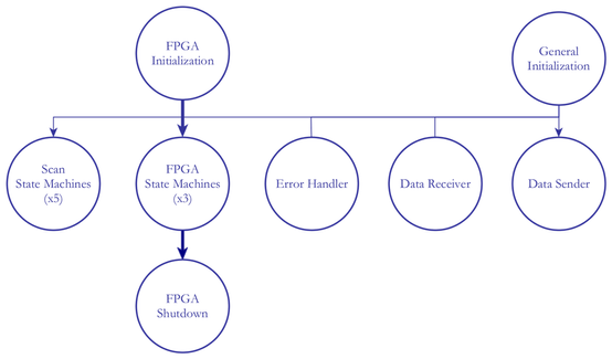
The Real-Time Algorithm has initialization blocks that create command queues for every module below and a specific FPGA Initialization Reference for FPGA States machine that need a memory position in order to FPGA execute correctly. When running, there is independent execution for every block. Finally, when shutting down, they can terminate their own executions, except the FPGA state machines that need to clear the memory positions associated with the previous execution.
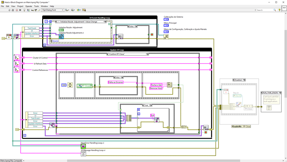
For the Host, its architecture is equivalent to the one employed in the RT modules: a queue-driven state machine. In addition, the code also has an event-driven structure to direct the system to the desired action. Therefore, one section executes commands, and another creates them, which characterizes an advanced producer-consumer structure, also known as QMH (or Queued Message Handler) and widely used in LabVIEW applications. The next figure shows the Host structure. It has a bootup functions that prepare two parallel loops, the producer and the consumer.
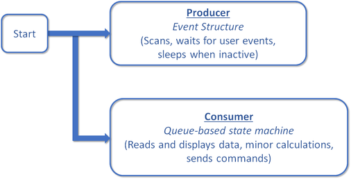
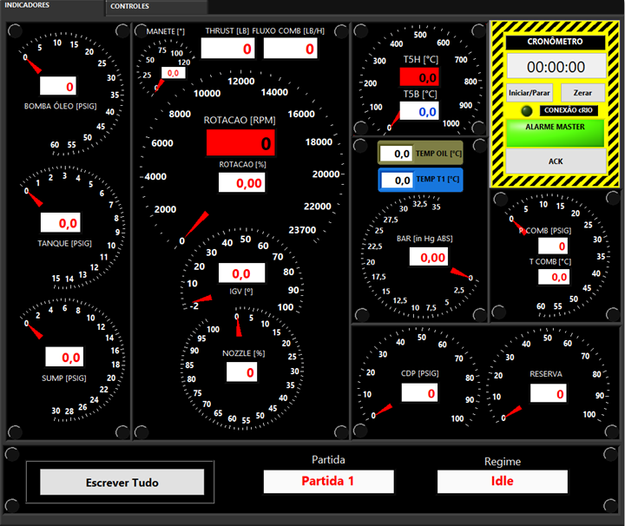
The Host can configure the system by changing parameters such as the data rate. It also sends commands to all lower levels of the architecture. Its indicators resemble analog pointers to facilitate operators’ transition from old systems, similarly to what happened in the test cell modernization.
The figures below are different prints of the main screen of host and its configurations screens, where every variable can be read and saved in a spreadsheet by using the lower buttons.

These are configurations screens, here the user can change parameters related to some variables, such as offsets. The interface of the right-hand image allows hardware connection and when to start or stop acquisitions.
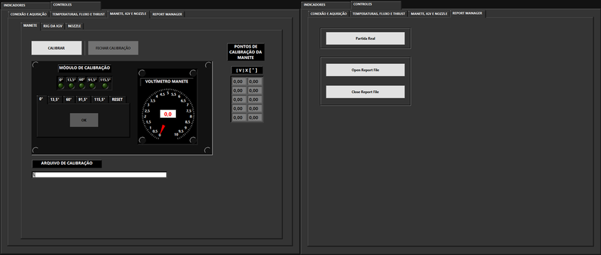
There are also functionalities to calibrate some variables, such as the lever position, and to load the report file that will be used during a specific test session.
The Conclusion:
This application was the first to address the logistical bottleneck inside the defense chain. Although test benches are efficient, robust and complete, many episodes are affected by the lack of mobility of the structure. This means it can then be employed on several bases far from its fixed workshop. It is important to mention that this technology can be extrapolated to other types of remote operations, such as those on aircraft carriers and allied bases abroad. When considering civil aviation, the possibilities increase substantially. Finally, such a development does not prevent the use of the same algorithm on other engines.
Such system paves the way for improved logistics, where an engine does not have to be always moved anymore and simple repairs can be done in loco. This means its purpose of addressing several logistical issues was attained. This project also brought optimization in productivity, shortened testing time and enabled significant fuel economy, which means lower maintenance costs.
For future projects, it is possible to implement all test routines recommended by the engine’s manufacturer, just as it already happens in the modernized test cell we talked about. There is also room for adding more complete configuration interfaces, or even use model analysis and machine learning to predict failures. Now that the Brazilian air force knows these tools, it may develop entirely new systems.
One of the project challenges was employing FPGA for the first time, which involved a different approach and a certain period to correctly understand its programming methods; formal training proved itself essential on this aspect. Secondly, the compact nature of the system also required more attention on what variables had to be acquired, where we depended on operator’s know-how to properly assess every needed measurement.
Sergeant Ribeiro and Professor Brincalepe played a key role during the development of the project, both in the academic area and with technical issues. On an ending note, it is important to highlight the fact the whole software was developed by students during the final year of their graduation course as Control and Automation Engineer.
So many positive results meant that the development was successful and brought both time and fuel economy. Besides, this development was published in an international Conference, the IEEE AUTOTESTCON 2018, and hopefully will contribute to future endeavors.
Time to Build:
The whole material used on this project arrived in early February. Consequently, the development of the project started from there, both hardware and software. The final delivery date was already stipulated, since the correlation exercise had been scheduled with engineers of the US Air Force (USAF), where the portable system would be used and approved for later uses. Before being used, each module needed to go through a calibration process that would last about a month. Everything should be ready to be sent to the Air Force calibration area at the end of June. Therefore, the entire project was done in exactly five months. Despite the small amount of time, the system was a success, receiving praise throughout the whole process of correlation.
Optional:
LabVIEW Code:
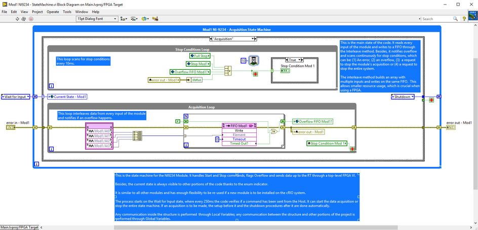
Project Construction:
Additional Photos:

References:
RAMOS, Henrique KM et al. Portable test system for jet engines through FPGA technology. In: 2018 IEEE AUTOTESTCON. IEEE, 2018. p. 1-8.
DOI: 10.1109/AUTEST.2018.8532548
