From Friday, April 19th (11:00 PM CDT) through Saturday, April 20th (2:00 PM CDT), 2024, ni.com will undergo system upgrades that may result in temporary service interruption.
We appreciate your patience as we improve our online experience.
From Friday, April 19th (11:00 PM CDT) through Saturday, April 20th (2:00 PM CDT), 2024, ni.com will undergo system upgrades that may result in temporary service interruption.
We appreciate your patience as we improve our online experience.
11-26-2012 03:41 PM
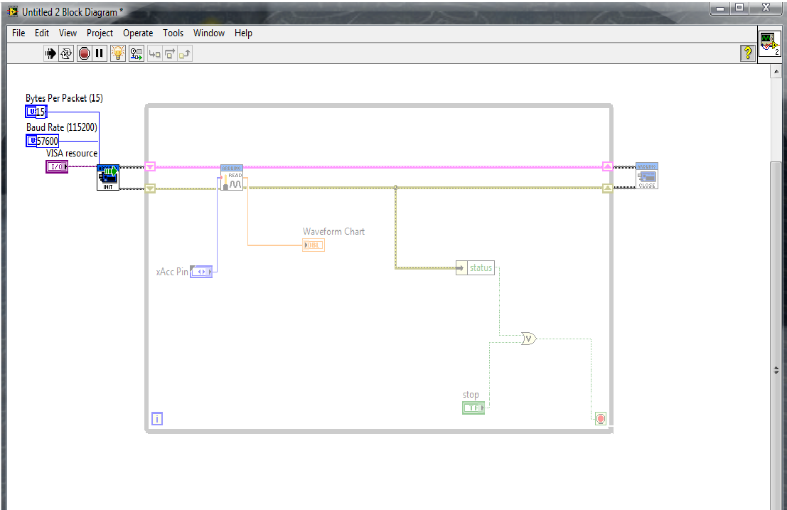
Hey guys, LabView novice here. I have a 5DOF IMU (3-axis accelerometer, 2-axis gyro), and I'm trying to filter and manipulate the analog signal it is outputting using LabView. I expanded the simple "Analog Read Pin" example that came with LIFA so that it will graph all 5 values, but I'm having trouble applying filters.
I have the feeling it's a data type issue, as I am fairly confused about the difference between regular data, dynamic data, waveforms, arrays, etc.. when it comes to the filter. I simply want a low-pass filter to filter out the noise from vibration. Any help would be greatly appreciated. I attached my VI.
Solved! Go to Solution.
11-26-2012 07:25 PM
The easiest method to use to filter your signal is an Express "Filter" . Found at Express > Signal Analysis > Filter. To use the filter you need to convert the Analog Pin Double data type to an Expres Dynamic data type using a "Convert to Dynamic Data2' function.
If you look in the last message in the Converting Analog Input to Frequency" thread there is an example, "Analog ReadPinVers2.VI, that uses the Express "Tone" VI. Maybe this will help you.
Double is a regular data type.
All of the Expres VIs require Dynamic data.
Waveforms data type, WDT, is data that includes timing information.
hrh1818
11-27-2012 12:10 AM
Thanks for the help! So I started back with the basic Analog Read Pin again just to try to get it working with one pin first. I converted the double to dynamic data and fed that into an express filter. The filter is a lowpass butterworth 3rd order with a cutoff frequency of 10hz. When I run it I get this error:
---
Error -20023 occurred at Filter->LabVIEW Interface for Arduino.lvlib:Arduino Analog Read Pin.vi
Possible reason(s):
Analysis: The following conditions must be met: 0 < f_low <= f_high <= fs/2.
---
This sounds like a Nyquist criterion issue, however, I don't even know what the sampling frequency is as there was no option to set that anywhere. The baud rate is set to 115200 but I don't know how to change the sampling rate.
It works if I set the cutoff frequency to anything under 0.5Hz, indicating that the sampling frequency is at 1Hz, but that can't be true because the output is being displayed much faster than that when I don't have the filter in there.
Any thoughts?
11-27-2012 06:43 PM
I gave you some bad advice. The Express "Filter" VI won't work in this application. The Expres VI requires timing information to be included in the data. If no timing data is included the Express "Filter" VI assumes the sample rate is 1 sample per second. Furthermore it is designed to filter data a block at a time. It is not designed to filter data continuously like an analog filter.
Labview does have Point by Point Filters. See Functions Palette > Signal Processing > Point by Point > Filters > Butterworth. You will need to open the front panel of the Butterworth Icon to set the filter parameters. Or you could add controls to your Main VI front panel to set frequently used parameters. Be sure to read the Context Help for this filter.
Attached is a low pass filter example and an analog speed test VI. The speed test measures how long it takes to sample an analog signal 1000 times.
Use the data to estmate your computers analog sample rate.
hrh1818
11-28-2012 01:27 AM
That worked beautifully! Thanks a lot. I had to play around with the cutoff frequencies for a while to get it to work well, but it turned out great. I attached a snapshot of the raw vs. filtered data.
06-03-2013 05:13 PM
Hi
hrh1818
Can you please convert the examples for LB2010? I need to improve the filtering of the sharp IR sensor, now i have a noise near 1cm even with a capacitor between Vcc and GND.
Best
CPalha
06-03-2013 05:38 PM
Here are those two files saved for LabVIEW 2009.
06-03-2013 05:39 PM
Thanks for the fast answear.
CPalha
08-15-2013 01:07 PM
how do you get the graph?can you show me the arduino program and also labview program?
08-15-2013 11:05 PM
i'm sorry but i'm facing this problem...when i'm running the program,it got green arrow and nothing display at the graph...pliz help me .tq
