From 04:00 PM CDT – 08:00 PM CDT (09:00 PM UTC – 01:00 AM UTC) Tuesday, April 16, ni.com will undergo system upgrades that may result in temporary service interruption.
We appreciate your patience as we improve our online experience.
From 04:00 PM CDT – 08:00 PM CDT (09:00 PM UTC – 01:00 AM UTC) Tuesday, April 16, ni.com will undergo system upgrades that may result in temporary service interruption.
We appreciate your patience as we improve our online experience.
11-21-2013 06:02 AM
Hi Guys,
For the testing of my chip, I have decided to use cRIO-9024 system. First time I am using labview and compact RIO system.
Your suggestions or links for the tutorial would be really helpful wrt my questions as below:
1. I have to provide different analog output value at each clock event, It would be easy if I can import these values from a file and at each clock event I can provide that to analog output pin.
What is the best way to import files which contain the vol value in floating point ? And how can I sample each value at clock event from it?
2. Another option, if I can store different analog value in an array and then pass this to output pin with each clock event. Please let me know any sample code for the array usage.
3. Any tutorial which explains how to use clock to sample any data.
4. I think, it would be very common usecase, in which you provide analog output at each clock event and also grab some analog input , if you have any sample usecase please send it to me.
Thanks,
Chetan
11-21-2013 03:25 PM
Hi Chetan,
Are you trying to synchronize your analog output to the onboard 40MHz clock, or an external clock?
Figure 5.5 in Section 3 of the CompactRIO Developer's Guide shows a basic example of reading an analog input value (or, you could easily be writing to an analog output value, instead) at a each clock event. In this example, the source clock is the 40MHz base clock, and the analog input node is being sampled at a rate defined by the "Sample Delay (tick)" control. If the control is set to 50, the analog input node would sample every 50 ticks of the 40MHz clock.
There is additional information in Lesson 5 - Timing an FPGA VI in the LabVIEW FPGA training course, which you can access online, for free if you have purchased SSP with your LabVIEW software.
If you want to read your data from a file, before writing it to the analog output node, you can read from the file on your host processor, and stream it to the FPGA using a DMA FIFO. See the LabVIEW shipping example "Streaming (DMA)" in the Example Finder under FPGA > CompactRIO > Fundametnals > Data Transfer and Storage > Host to FPGA. In this example you are reading one data point off of the FIFO at a defined clock interval.
You can also use an array, similar to how you would use an array in regular LabVIEW. LabVIEW FPGA 2012 and later support SGL floating point datatypes.
11-21-2013 11:14 PM
Thanks Matt,
I need slower clock ~1MHz, so I can use on board clock.
I am not able to access LabVIEW training courses. I'll try all the options which you have suggested and will let you know.
Can I generate traingular wave on board with 10K frequency and sample this with 1 MHz clock and pass this to analogout module with each event? any testcase please?
Thanks,
Chetan
11-22-2013 10:25 AM
Here is an example of how to generate a triangle wave using a LUT (look-up table) in LabVIEW FPGA. You can control the clock rate by using timing functions, as described in online training, and also in the CompactRIO Developer's Guide linked above.
11-24-2013 05:36 PM
Hi Matt,
Thanks for the link. It seems really helpful. I'll try this on my platform.
Best regards,
Chetan
11-25-2013 05:56 AM
Hi Matt,
I am trying to mix both digial and analog in my VI but it's a lot confusing.
I am attaching simple pseudocode which I am trying to implemnet in VI , that contains few analog signal and 1 digital signals and they are sync with the clock (lets say=10KHz).
Caould you please suggest some sample VI for this or demonstrate how can I proceed.
Thanks a lot!!
Chetan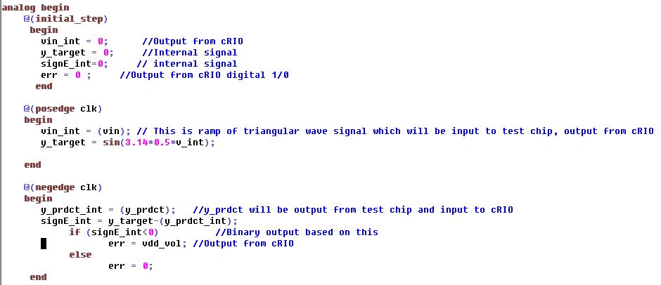
11-25-2013 11:58 PM
Hi Matt,
I am facing a weired issue. according to below link:
http://zone.ni.com/reference/en-XX/help/371599G-01/lvfpgaconcepts/performing_basic_i_o/
if I need to send any analog output value using C series module, I need to provide corresponding binary value. So I have created an array to send the binary data (-32768 to 32767) corresponds to '-10V to 10V' to generate ramp. But what I found that it doesn't work that way, instead if I provide direct no between -10 to 10 then it shows on oscilloscope but the problem is I can only provide integer in an array and I can't generate intermediate voltage like 2.2,3.1,..etc. And if i want to generate any voltage between 0-1, I can't.
Attaching the VI which I am using. Thanks a lot for your help.
Best regards,
Chetan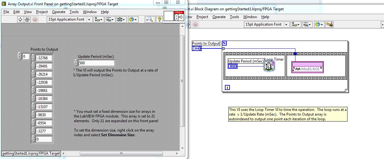
11-27-2013 11:10 AM
Hi Chetan,
Analog modules have 2 "modes" for access, fixed point and Int. We used to only offer Int but fixed point can be (slightly) more intuitive and we added that as an option a few years ago. The IO node you are using is currently set for fixed point input. You can tell because the text (and wires) for fixed point will be grey (int will be blue). You can also tell that LabVIEW is changing the data type for you by the small red dot where you wired into the node. This is why you are only seeing voltages from -10 to 10. You can either change the mode of the IO node to Int (I think you can right click on the IO node to change) or you can change the values in your array to fixed point numbers (right click on one the cells and there will be an option to change the data type). If you want to figure out an appropriate fixed point radix setting you can create a control from the IO node and then check the properties.
I hope this helps. Good luck.
Todd
11-28-2013 07:09 PM
Hi Todd,
You are right, I have changed the module properties as mentioned in below for your ref:
http://forums.ni.com/t5/Real-Time-Measurement-and/ni-9263-voltage-output/td-p/1744482
It was really helpful.
But new trouble, getting compilation error for my other FPGA code:
LabVIEW FPGA: The compilation failed due to a xilinx error.
Details:
ERROR:HDLCompiler:104 - "\NIFPGA\jobs\hK27Ns1_i3j35Xu\TheWindow.vhd" Line 787: Cannot find <nifpgaag_ni_munge_tab_tb> in library <work>. Please ensure that the library was compiled, and that a library and a use clause are present in the VHDL file.
ERROR:HDLCompiler:854 - "\NIFPGA\jobs\hK27Ns1_i3j35Xu\TheWindow.vhd" Line 108: Unit <behavioral> ignored due to previous errors.
VHDL file \NIFPGA\jobs\hK27Ns1_i3j35Xu\TheWindow.vhd ignored due to errors
-->
Total memory usage is 200924 kilobytes
Number of errors : 2 ( 0 filtered)
Number of warnings : 2 ( 0 filtered)
Number of infos : 0 ( 0 filtered)
Process "Synthesize - XST" failed
Todd & Matt, Any idea about it?
Thanks,
Chetan
12-02-2013 08:16 AM
Hi Chetan,
I don't think these are errors you should be seeing (ie it is likely not caused by something you did in your code). When you compile your LabVIEW FPGA code the program does a number of steps automatically, including generating files and then sending those to the Xilinx complier. This sounds like somewhere in that automated proces something went wrong. If you keep seeing this error I would recommend you call NI tech support.
Some things you can try:
Compiling again (obvious and you probably already tried)
Try compiling a blank VI (just to verify that it is not something specific to your code)
Try using a different compiler if possible (for instance do you have access to cloud compile option or a different machine)
Uninstalling and reinstalling the Xilinx tools (brute force and may not be needed but this often fixes problems that can be hard to track down otherwise).
If you are still getting the error it would also be good when you speak with tech support to indicate where in the compile process it failed. When you compile it pops-up a window that indicates the multiple steps (file generation, etc) and then calls the Xilinx tools. The Xilinx tools also have a progress indication. Any info from this process may be helpful for support.
Good luck.
Todd
