- Subscribe to RSS Feed
- Mark Topic as New
- Mark Topic as Read
- Float this Topic for Current User
- Bookmark
- Subscribe
- Mute
- Printer Friendly Page
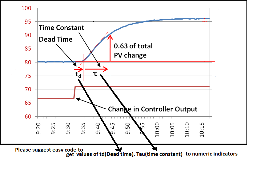
Please suggest code or example to find the time period of the process as shown in image.
07-28-2014 04:07 PM
- Mark as New
- Bookmark
- Subscribe
- Mute
- Subscribe to RSS Feed
- Permalink
- Report to a Moderator
Please suggest code to find the time period of the process as shown in image.
or any example from which i can have idea.
Regards
MMS79
mms79
07-28-2014 04:22 PM
- Mark as New
- Bookmark
- Subscribe
- Mute
- Subscribe to RSS Feed
- Permalink
- Report to a Moderator
These types of requests are typically fielded at forums.ni.com. See attached for some tools. I've used the following approach to measure the time between 2 triggers. Drag the following snippet PNG onto a blank LabVIEW diagram to convert to code:
Certified LabVIEW Architect
TestScript: Free Python/LabVIEW Connector
One global to rule them all,
One double-click to find them,
One interface to bring them all
and in the panel bind them.
07-28-2014 04:23 PM
- Mark as New
- Bookmark
- Subscribe
- Mute
- Subscribe to RSS Feed
- Permalink
- Report to a Moderator
You're looking at a "bump test". Read the tutorials on www.controlguru.com for a good start. You can conduct this test with a simple LabVIEW loop that acquires all the variables (SP, PV, MV) with your choice of I/O driver (NI-RIO, NI-DAQmx, etc.) and plots them against one another.
07-28-2014 04:25 PM
- Mark as New
- Bookmark
- Subscribe
- Mute
- Subscribe to RSS Feed
- Permalink
- Report to a Moderator
Those aren't triggers. They're PID control variables. The blue line is the measured output of the plant (PV) and the red line is the input signal to the plant (or another signal that maps linearly to it, MV).
07-28-2014 04:36 PM
- Mark as New
- Bookmark
- Subscribe
- Mute
- Subscribe to RSS Feed
- Permalink
- Report to a Moderator
There seems to be confusion about whether the OP is looking for instructions for conducting a bump test or how to analyze that step response and present in indicators. MMS79 - echo back with any further questions.
Certified LabVIEW Architect
TestScript: Free Python/LabVIEW Connector
One global to rule them all,
One double-click to find them,
One interface to bring them all
and in the panel bind them.
07-28-2014 04:52 PM
- Mark as New
- Bookmark
- Subscribe
- Mute
- Subscribe to RSS Feed
- Permalink
- Report to a Moderator
Thanks for the reply,
as Staab_Engineering suggested it is PID control variables of level control loop.
i want to find the model of level control loop with first order system in labVIEW,
for which i require dead time and time constant of process for further calculation.
How can i get the same in seconds in numeric indicator,
please suggest code or example for same.
Regards
MMS79
mms79
