- Subscribe to RSS Feed
- Mark Topic as New
- Mark Topic as Read
- Float this Topic for Current User
- Bookmark
- Subscribe
- Mute
- Printer Friendly Page
Clip Generation (SPI)
02-16-2015 04:32 AM
- Mark as New
- Bookmark
- Subscribe
- Mute
- Subscribe to RSS Feed
- Permalink
- Report to a Moderator
Hi,
I try to create a CLIP which contain a SPI communication.
So I wrote a HDL code which integrates my SPI communication, the bloc have some I/O like clock, Dataready, Reset,... The HDl code was checked on Modelsim and on Labview (chek syntax). All seems OK.
After this, I created my XML, with the XML generator to generate my CLIP node. Here too, the XML generation seems OK, and I have my node with all my IO ( except Clock and nReset).
We arrive to my issue, now I try to use my CLIP in a small VI (just to check). The compilation "failed" due to : Timing violation.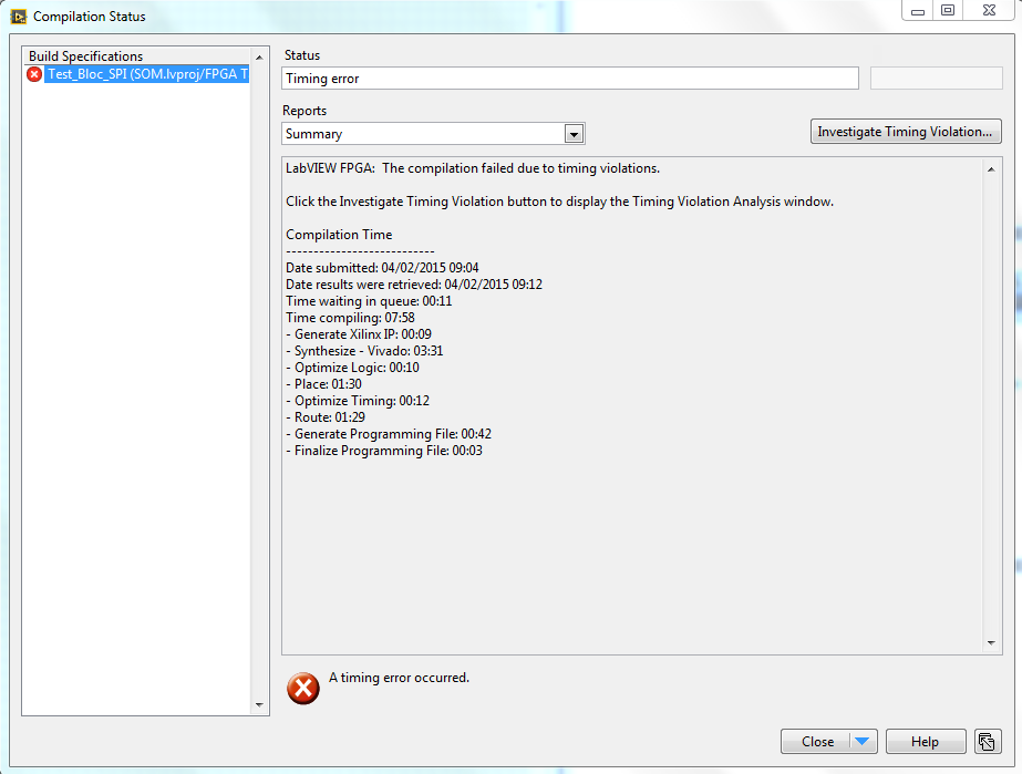
Investigate Timing Violation...:

When I try to modify my VI by removing some I/O, sometimes I succeed to compile but the issue doesn't depend on a particular I/O. For me, it's just the number of I/O present on my VI which creates the problem. I need all my IO to have my SPI communication...
I tried to acces my I/O one by one with a flat sequence, and with a timed loop. The problem is alaways present.
If you could advise me to resolve my issue of timing violation.
For information, I realized the DemoClipAdder, and I had no problem so I have to do something wrong but what?
Thanks
02-16-2015 09:12 AM
- Mark as New
- Bookmark
- Subscribe
- Mute
- Subscribe to RSS Feed
- Permalink
- Report to a Moderator
Can you share a screenshot of your CLIP in the project and the VI block diagram that fails to compile?
Are you using a socketed CLIP (required for HDL to access IO directly) or a non-socketed CLIP? Which carrier board are you using? The Development Kit Reference Carrier Board?
When creating a socketed CLIP for the SOM, you must use the CLIP Generator tool included with LabVIEW. The generator is available from the FPGA target right-click menu in the project or from the Start Menu in Windows. After the CLIP generator creates the high-level template for your target, you can then modify the generated HDL, Timing Constrains, and XML to add your SPI IP.
-spex
National Instruments
To the pessimist, the glass is half empty; to the optimist, the glass is half full; to the engineer, the glass
02-16-2015 12:19 PM
- Mark as New
- Bookmark
- Subscribe
- Mute
- Subscribe to RSS Feed
- Permalink
- Report to a Moderator
I use the the SBRIO-9651. What did you mean by socketed CLIP or non-socketed CLIP? I'm not sure to understand the difference. For me it's a non-socketed CLIP because I create this CLIP.
I will explain my method to create CLIP because when I try to launch the sbRIO CLIP genrator, nothing happens.
So firstly, I right-click on the fpga target-> Properties. I create a new file XML:
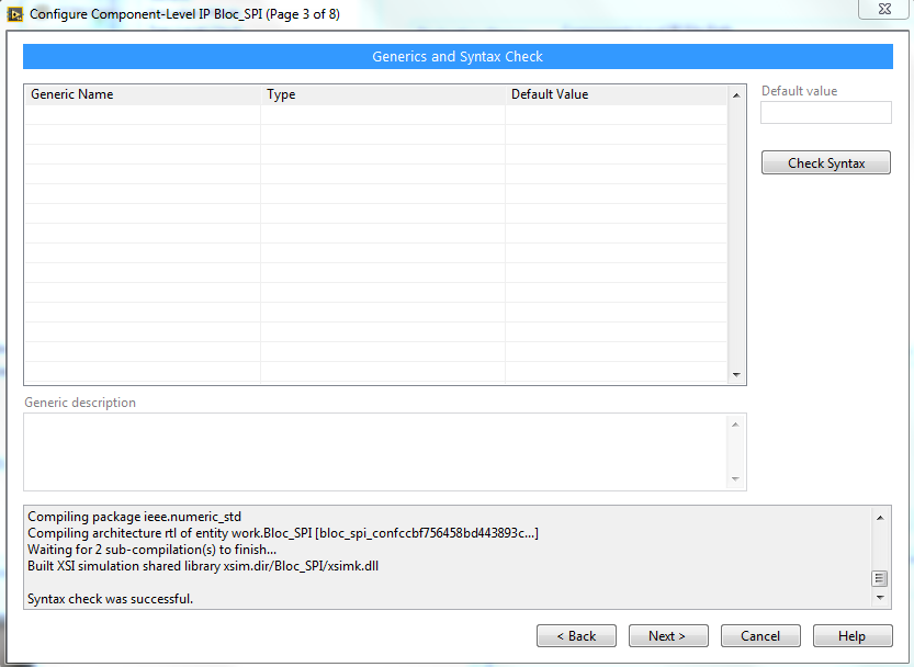
Secondly, I check my VHDL when I create the XML:
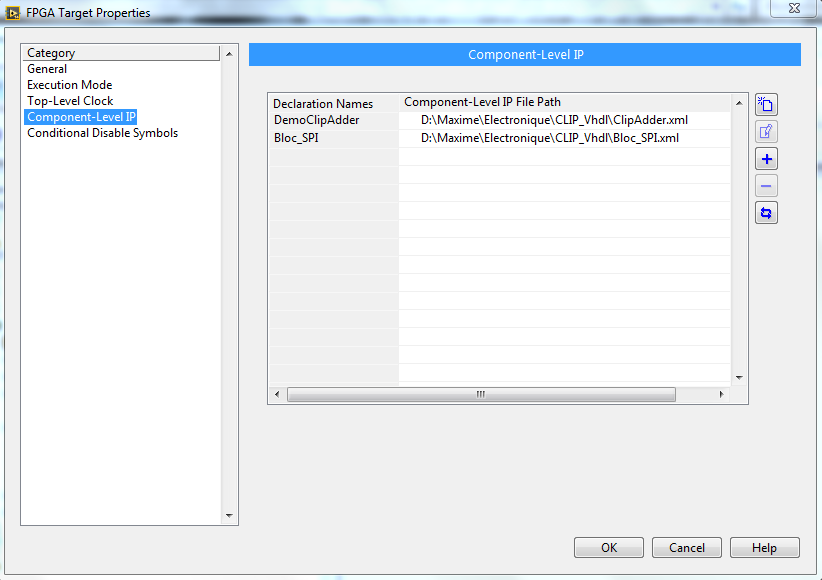
When my xml is generated, I add my CLIP:
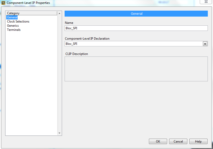
Finally, I have my CLIP (Bloc_SPI) in my project:
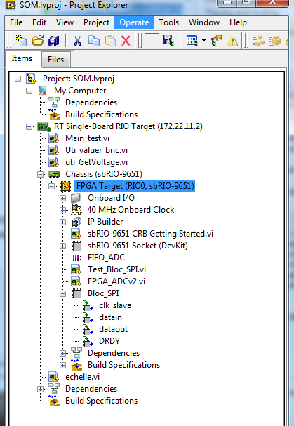
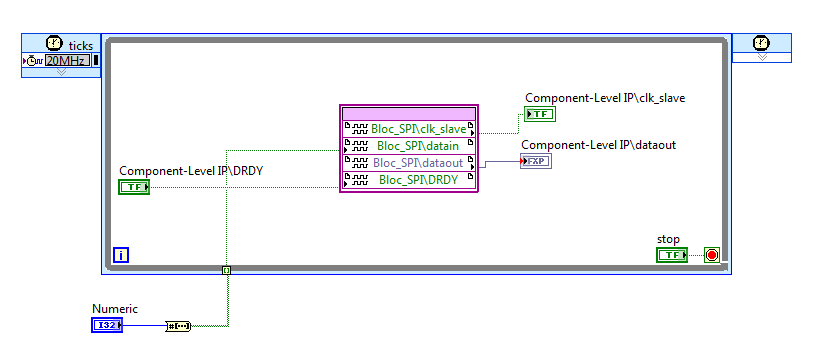
To finish, my VI:
Sorry for all the pictures, but I think that patterns better than words.
So I begin by the HDL, I don't try to modify a generated HDL. For the Timing Constraint, I don't modify the default value. The issue is maybe here...
Thanks SPEX for your help.
MMO
02-16-2015 01:23 PM
- Mark as New
- Bookmark
- Subscribe
- Mute
- Subscribe to RSS Feed
- Permalink
- Report to a Moderator
What did you mean by socketed CLIP or non-socketed CLIP?
The 9651 has a "socket" named "sbRIO-9651 Socket". For this test, you are using the "DevKit" Socketed CLIP in the 9651 Socket (which we provide). Then you added your own CLIP (unsocketed) and it looks like you named it "Bloc_SPI". It looks like you read and write to the CLIP signals in a 20MHz SCTL (which I'm guessing is derived from the 40MHz clock).
when I try to launch the sbRIO CLIP genrator, nothing happens.
That part worries me. What is supposed to happen is that when you click "Launch sbRIO CLIP Generator", it's supposed to launch the executable at "C:\Program Files\National Instruments\NI-RIO\CLIP Generator" (or wherever you installed your NI software). My guess is that there was a problem with the path or permission settings.
The CLIP generator generates XML and VHDL that you can modify. It's designed to give you a starting point so that you can work from a working simple CLIP and extend it for your specific application.
In summary, your setup is a little weird (you really should modify generated HDL from the CLIP generator instead of writing your own from scratch), but I don't see anything that is incorrect. If you send me your files, I can try to reproduce the issue and see if I can figure out what is going wrong here.
My recommendation in the meantime is to follow a more traditional route to implement your application and see if you can get it working.
1. Remove your CLIP from the project.
2. Run CLIP Generator (if the right click menu isn't working then just navigate to the path I mentioned and run the executable). You can assign your signals to '0' or open instead of hardware pins.
3. Assign your CLIP to the socket using the socket's property page.
4. Change your FPGA diagram to use your new socketed CLIP IO Nodes,
5. Make sure it compiles
6. Copy your SPI logic from your old CLIP HDL to the newly generated HDL and connect the signals to it.
7. Make sure it still compiles.
Hopefully that will work. If you have any questions about settings in the CLIP generator you can consult the documentation.
PS. I noticed you used a FXP data type. We don't support that in the CLIP Generator. How important would it be to you to add support for them in the future?
02-18-2015 09:14 AM
- Mark as New
- Bookmark
- Subscribe
- Mute
- Subscribe to RSS Feed
- Permalink
- Report to a Moderator
Hi MMO,
Tannerite recently posted a more detailed presentation regarding how we expect developers to use the CLIP generator. I think it has useful information that can help your overall efforts.
https://decibel.ni.com/content/docs/DOC-41410
Have you been able to get your CLIP generator loaded as nturley explained in his post?
Regards,
spex
National Instruments
To the pessimist, the glass is half empty; to the optimist, the glass is half full; to the engineer, the glass
02-20-2015 09:22 AM
- Mark as New
- Bookmark
- Subscribe
- Mute
- Subscribe to RSS Feed
- Permalink
- Report to a Moderator
Hi nturley and Spex,
The method that nturley gave me and your link allowed me to success to create a Clip which integrate my HDL code.
My principal issue was a bad management of my process which worked on rising and falling edge ( process which compile on Modelsim but not under Labview)
Your help ( nturley and Spex) allowed me to understand the difference between Non-socketed CLip and socketed Clip, and to understand the subtleties.
For nturley, it's not a problem for me that the FXP data type isn't supported.
So thank you for your help, I hope that this post help others guys to build a Clip.
Regards,
MMO
