- Document History
- Subscribe to RSS Feed
- Mark as New
- Mark as Read
- Bookmark
- Subscribe
- Printer Friendly Page
- Report to a Moderator
- Subscribe to RSS Feed
- Mark as New
- Mark as Read
- Bookmark
- Subscribe
- Printer Friendly Page
- Report to a Moderator
myDAQ Laser Wall
myDAQ Laser Wall
Created By:
- Chris Faulkner
- Electrical Engineer, Baylor University
- RF Baseband Intern
- Daniel Collotte
- Electrical Engineering, University of Florida
- ELP Engineering Intern
- Electrical Engineering, University of Florida
Introduction:
MyDAQ provides an unique platform that has a vast amount of integrated functionality while maintaining its ease of use thanks to Labview support. For our project we wanted to make use of the data acquisition capabilities as well as the units generation capabilities. We decided to use a touch pad to control a laser mounted on a servo and have the laser track the movement of the user input on the touch pad. This allows the user to draw images using the touch pad and have the laser trace out the image on a wall, building, even the clouds!
Purpose:
This tutorial will provide the user with a tour of both the analog and digital IO capabilities of the myDAQ.
The goal was to use a resistive touch pad to control a laser pointer mounted upon two servos connected in a pan/tilt configuration. This allows for a 2D drawing on surfaces.
Due to limitations of the myDAQ we can only generate one pulse width modulated signal for servo control. This effectively limited our project to only a single servo thus only a 1D drawing area. This was compensated for by adding touch activation to the laser so now the laser is activated by pressing on the touch pad. This demonstrates the generative abilities of the myDAQ by having to send both a PWM servo control signal and varying DC analog voltage for the control of the laser.
Equipment:
-Resistive Touch Pad for NDS $2.58
-4 AA batteries $1.00
-AA battery holder $1.00
-SG90 servo $2.89
-NPN Darlington BJT $1.00
-1k ohm resistor $0.50
-5mW green laser pointer $2.03
-spare capacitors (optional) $0.00
-alligator clips $2.00
- spare wire, hot glue gun, plastic object( for mounting to)
Video Demonstration:
http://www.youtube.com/watch?v=4Q7IDzw9kyo&feature=youtu.be
Setting Up Hardware:
1. Wire the devices as shown in the diagram below.
2. In addition, wire together the myDAQ’s digital and and analog grounds, and ground the AI’s negative inputs.
3. Connect AI0+ to DIO4, and AI1+ to DIO4
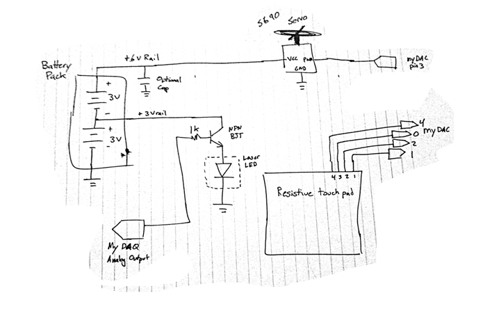
Figure 1: Hardware schematic
Setting Up Software:
The program consists of two routines:
1. The Touchpad Routine: This routine rapidly switches the DIO pins connected to the touch pad between the two circuit diagrams below. When a DIO pin is not being used to provide +5V or GND, it is set as an input. The corresponding AI pins are used to read the voltage caused by the resistive divider created when a finger touches the panel.
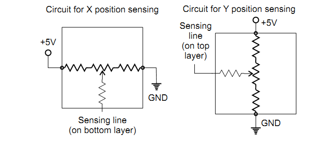
Figure 2: Touchpad sensing schematic from http://www.sparkfun.com/datasheets/LCD/HOW%20DOES%20IT%20WORK.pdf
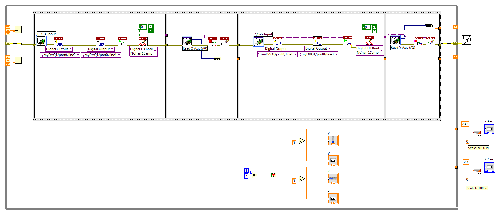
Figure 3: Touchpad VI
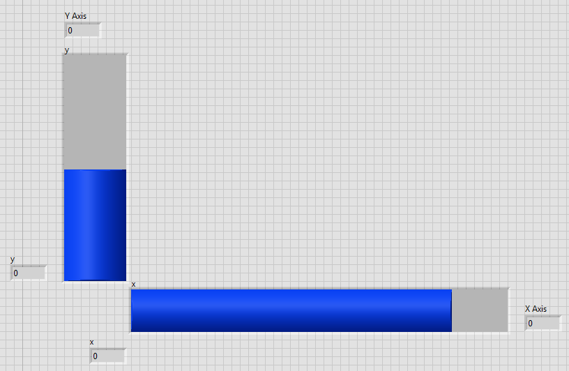
Figure 4: Touchpad Front Panel
2. The Translation Routine: This routine calls the touchpad routine as a subvi, and uses the X value to turn on the laser, and the Y value to vary the duty cycle for a PWM signal to move the laser along the wall. This is the main VI you run to operate the laser wall.

Figure 5: Main VI
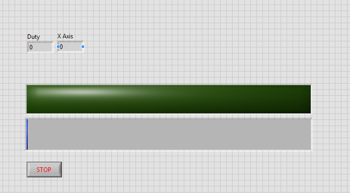 Figure 6: Main Front Panel
