- Document History
- Subscribe to RSS Feed
- Mark as New
- Mark as Read
- Bookmark
- Subscribe
- Printer Friendly Page
- Report to a Moderator
- Subscribe to RSS Feed
- Mark as New
- Mark as Read
- Bookmark
- Subscribe
- Printer Friendly Page
- Report to a Moderator
The Vehicle Networking Demonstration System
The Vehicle Networking Demonstration System
Contact Information
University: Jilin University, China
Team Member(s): Jun Wang, Lifei Duan, Dian Lei, Fangming Lou, Zhangyong Guo, Shuwei Zhang, Lanxin Geng
Faculty Advisors: Professor Zhenhai Gao
Primary Email Address: wangjunrabbit@gmail.com
Primary Telephone Number (include area and country code): (86) 13844853270
Project Information
Title: Vehicle Networking Demonstration System
Description:
<insert brief description in 1-2 sentences>
The objective of the project is to demonstrate the advantages of the coming Intelligent Transport System (ITS).
Products:
<insert list NI hardware and software used in project>
Vehicle Hardware: NI Robotics sbRIO Starter Kit, NI Single Board RIO-9631
Vehicle Software: Labview 2009, Digital Filter Design Toolkit, Advance Signal Processing Toolkit, Robotics Module, PID and Fuzzy Logic Toolkit, FPGA Module
Traffic Control System Hardware: PXI 1042Q, PXI 8106
Traffic Control System Software: Labview 2009, NI Vision Development Module, NI-VISA
The Challenge:
<insert the description of your project>
In order to demonstrate the function of Intelligent Transport System (ITS), we established an indoor mini traffic system, which involves pedestrian, vehicles and roadway.
The roadway comprises of straight and cross road. The straight lane consists of four traffic lanes, 10 meters in length and 3 meters in width totally. And the cross road makes up of two elliptical tracks with an area of 4m × 5m, including four intersections. There are traffic lights at two intersections.
There are seven robotic vehicles in the simulation environment, the controller of which is NI sbRIO 9631. Of all the robotic vehicles in the project, two robots are NI Robotics sbRIO Starter Kit; the others are assembled entirely by ourselves. Environment perception sensors including camera, magnetic sensors, ultrasonic sensors and wireless communication module are integrated into the robotic vehicle. Based on magnetic navigation technology, machine vision technology, wireless communication technology and automatic control technology, the robotic vehicles have achieved three primary functions including automatic track, vehicle to vehicle communication (V2V), vehicle to infrastructure communication (V2I), and we developed a demonstration system for Network of Vehicles on the basis of these functions. A part of Cooperative Vehicle-Vehicle Systems (CVVS) and Cooperative Vehicle-Infrastructure Systems (CVIS) are implemented in the simulation environment with the Network of Vehicles.
The Solution:
<how does your project work>
<explain the benefits using LabVIEW and NI tools>
<insert image(s) of project with captions>
<insert video links here>
The project demonstrates the advantages of the future Intelligent Transport System.
System Architecture of the Demonstration System
The demonstration system is broken down into three main components: road traffic facilities, robotic vehicle, and intelligent roadside infrastructure, as shown in the figure 1.
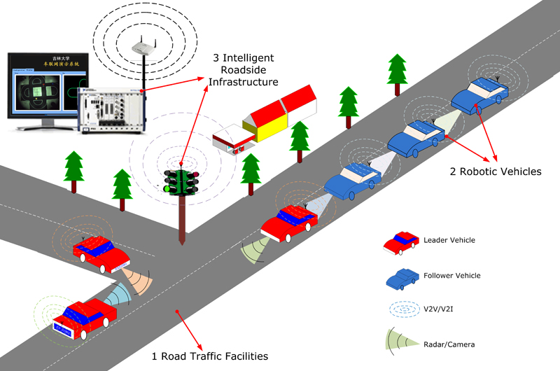
Figure 1 System Architecture of the Network of Vehicles
I. Traffic facilities
The road traffic facilities which include roadway (as shown in figure 2), traffic lights (as shown in figure 3), and traffic signals provide a simulated traffic environment to robotic vehicles.
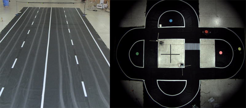
Figure 2 Road Traffic Facilities
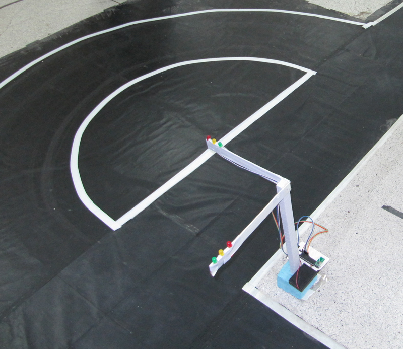
Figure 3 Traffic Lights
II. Robotic vehicles
Several robotic vehicles are used for simulating traffic flow. A robotic vehicle is made up of two main parts: the mechanical and the electronic part. As shown in figure 4, the electronic controller could be divided into four components.
- Controller - the controller hardware is based on NI sbRIO 9631.
- Wireless communication module - the module equipped on the robotic vehicle is for communicating with other robots and roadside infrastructure.
- Environment perception sensors, such as camera, magnetic sensors, ultrasonic sensors and so on.
- Actuators include the driver motors to move and servo motors to steer.
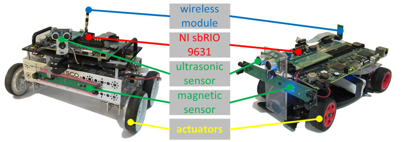
Figure 4 Robotic Vehicle
III. Intelligent roadside infrastructure
A NI PXI 8 slots chassis with a USB camera serve as the traffic management center in the project. It is not only able to detect the position of every vehicle in real-time, but also to communicate with other vehicles and control and monitor roadside infrastructure.
The location information of vehicle is essential for Cooperative Vehicle-Vehicle Systems (CVVS) and Cooperative Vehicle-Infrastructure Systems (CVIS). To acquire the vehicle’s location, a camera was fixed on the ceiling to ensure it can overlook entire track area and all moving robotic vehicles, as shown in figure 5. The image information is acquired continuously by PXI via USB, then processed in LabView. With the help of LabView Vision, the moving vehicle location was detected exactly and easily, the result is in figure 6. Then the location information is transmitted to corresponding vehicle via the wireless communication module.
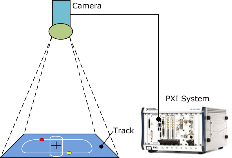
Figure 5 Robotic vehicle location detect system
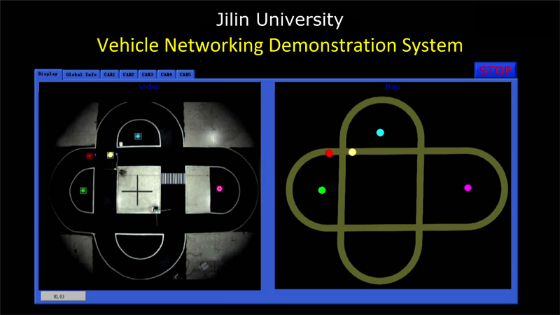
Figure 6 Result of position detection
Functions of the Vehicle Networking Demonstration System
Some typical functions of the Vehicle Networking Demonstration System as follow.
I. Automatic tracking
An enameled wire carried a 20 KHz sine current is paved beneath the centerline of the roadway. Based on the law of electromagnetic induction, there will be a magnetic field around the wire. Four coils acting as magnetic sensor mounted on the front of robotic vehicle are used for measuring the offset distance from the road centerline to vehicle center. The speed and steer angle of robotic vehicle are calculated based on the offset. The automatic tracking function of robotic vehicle is implemented by designing a nonlinear PID controller for speed and steer angle control respectively.
II. vehicle platoon driving
With the Cooperative Vehicle-Infrastructure Systems, vehicle platoon control can be realized, as shown in figure 7. This function can not only increases the density of traffic flow and augments road capacity, but also improves traffic safety and economize energy.
A real-time PID controller is designed to realize vehicle platoon driving by fusing the information from magnetic sensor and ultrasonic sensor with vehicle to vehicle communication information. The longitudinal spacing between vehicles is the key factor in vehicle platoon control. The appropriate longitudinal spacing is calculated in the project by taking into account the vehicle speed, road adhesion coefficient and the driving styles.
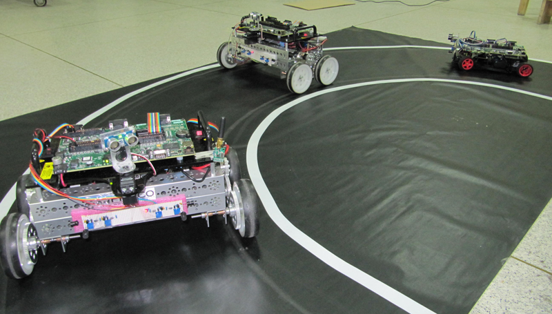
Figure 7 Vehicles platoon
III. Vehicle to vehicle communication & vehicle to infrastructure communication
Vehicle to vehicle communication (V2V) and vehicle to infrastructure communication (V2I) is the basis to establish the Intelligent Transportation System (ITS). The researches on V2V and V2I date from 1980s. V2V and V2I are proposed to mitigate the traffic accidents and optimize traffic control by offering traffic management center real-time traffic flow information.
In the project, we choose a RF product named nRF24L01 of Nordic Semiconductor to complete the function of wireless data communication. nRF24L01 is a single chip radio transceiver for the world wide 2.4-2.5 GHz ISM band. As shown in figure 8, the left one is wireless communication module mounted on robotic vehicle, the robotic vehicle’s controller sbRIO 9631 communicates with the module via SPI simulated by FPGA IO, and the robotic vehicle is able to exchange information with other vehicles and roadside infrastructure. The right one communicates with PXI chassis via USB.
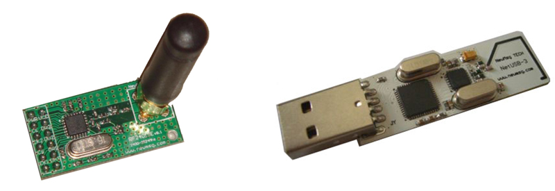
Figure 8 The wireless communication module
As shown in figure 9, a star network was built to link the traffic management center, all robot vehicles and roadside infrastructure together. All robot vehicles send their own state information to the traffic management center, the information is sent back to vehicles and traffic lights after the information is processed. The network assumes the task of information exchange between vehicles, roadside infrastructure and the traffic management center.
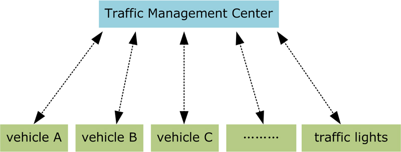
Figure 9 The topology of wireless communication network
IV. Cooperative Vehicle-Vehicle Systems & Cooperative Vehicle-Infrastructure Systems
Cooperative Vehicle-Vehicle Systems (CVVS) and Cooperative Vehicle-Infrastructure Systems (CVIS) is the trend of future Intelligent Transportation System (ITS). As a new technology emerged recent years, CVVS and CVIS have several advantages including avoiding traffic accidents, increasing road capacity and improving driving safety and comfort. The detailed functions of CVVS and CVIS as follows.
1) Green Light Sync Start
These sorts of travelling waves are common during urban traffic conditions. Traffic waves are a type of traffic jam, in other words, a moving wave of “jam”. Traffic waves are caused by many matters, such as intersection, traffic lights, merging lane, even an accident.
For example, at intersection, when the traffic signal turns to green, most of the vehicles remain standstill because all the vehicles in the same lane cannot move at the same time due to each driver is waiting for the car ahead to move. The traffic congestion will be alleviated if all vehicles depart at once when the traffic signal turns to green light. Green Light Sync Start aims to make the start faster. Based on CVIS, every driver can “see” the state and duration of traffic lights even the driver’s vision is limited or obstructed. All vehicles could move at once based on CVVS.
2) Cooperative Adaptive Cruise Control
It is one of the main research and development contents of ITS to improve the automotive active safety. Adaptive Cruise Control (ACC) is an automotive feature that allows a vehicle's cruise control system to adapt the vehicle's speed to the traffic environment. A radar system attached to the front of the vehicle is used to detect whether slower moving vehicles are in the ACC vehicle's path. If a slower moving vehicle is detected, the ACC system will slow the vehicle down and control the clearance, or time gap, between the ACC vehicle and the forward vehicle. If the system detects that the forward vehicle is no longer in the ACC vehicle's path, the ACC system will accelerate the vehicle back to its set cruise control speed. This operation allows the ACC vehicle to autonomously slow down and speed up with traffic without intervention from the driver. The method by which the ACC vehicle's speed is controlled is via engine throttle control and limited brake operation.
Cooperative adaptive cruise control (CACC) is an extension of ACC. In addition to measuring the distance to a predecessor, a vehicle can also exchange information with a predecessor by wireless communication. This enables a vehicle to follow its predecessor at a closer distance under tighter control. The results of research on CACC show an improvement of traffic-flow stability and increase in traffic-flow efficiency.
3) Dynamic Lane Management
Because of the increasing traffic capacity and limited road resources, conventional methods of traffic control cannot meet the demands of modern society. In order to alleviate the traffic jam that causes by the misdistribution of traffic flow and reduce the waste of capacity of intersections, dynamic lane management is proposed as an available way to resolve the problem. Dynamic lane management is able to adapt road resources to the need of traffic.
4) Virtual Traffic Lights at Intersection
In-depth traffic accident analyses highlights that human error, and more specifically not seeing the car coming or misinterpreting distance and speed is the primary cause of accidents taking place at intersection. The function of Virtual Traffic Lights aims to support both drivers and riders to compensate for these perception errors. Based on the broadcasted information including own location, speed and direction, the other vehicle is able to identify the car, and both vehicles can determine whether a critical situation can occur. Then vehicle will determine which vehicle has priority, base on rules of first come first go and the priority of vehicles etc.
5) Green Light Optimal Speed Advisory
The traffic light is connected to a roadside unit. Via this connection the traffic light can broadcast information to nearby vehicles. This includes information about the topology of the intersection and the phase schedule of each traffic light signal. Approaching vehicles can receive this information and calculate the optimal approaching speed. At optimal approaching speed, energy-efficiency is improved and stops may even be completely avoided.
6) Multi-priority Distribution to Vehicles
Special priority can be given to different classes of vehicles, such as emergency or public transport vehicles, or police vehicles. When it comes to situations affecting the safety of lives every minute and every second is crucial. Road users are obliged to make way for emergency vehicles (EVs) like ambulances or police cars and in practice are also willing to do so. However, hearing the siren does not always give information about the emergency vehicle’s location and direction early and precise enough to allow a proper reaction. A message provided by EV to help the driver on how to clear the road for the emergency vehicle even when the siren and lightbar may not yet be audible or visible.
7) Multi-Level Vehicle Information Monitoring
Vehicle information including position, speed and even the desired destination is available for traffic management system by communicating with individual vehicle. Therefore, it is possible for the management system to optimize the traffic efficiency. This opens the way to provide personalized routing guidance using instantaneous traffic information, safety alerts to vehicles in a certain area and speed recommendations to groups of vehicles.
Conclusion
Based on NI platform, our team has completed the project in less than two months. For mechanical engineers it is difficult to program on FPGA and RT controller. However, with the help of NI products, we success to acquire and process signals from all sensors mounted on robotic vehicle including ultrasonic sensor, magnetic sensors, digital camera, drive motors and achieve wireless data communication on FPGA. Thanks to the advantage of Labview’s graphical programming, it takes only two weeks for us to grasp the basic knowledge of programming on FPGA. In addition, NI products successfully integrate software with hardware seamlessly, so we can deploy control algorithm to the targets quickly and easily.
Controllers on robotic vehicles in the project are based on NI SingleBoard, control algorithms are programmed with Labview and involved FPGA module, RT module, Robot module and Advance signal process module. Multi-vehicle position detection is implemented using Labview Vision module on PXI chassis, as well as traffic control and monitor.
The Vehicle Networking Demonstration System is the combination of our idea and NI flexible, open technology. This system shows the new technologies and advantages of future Intelligent Transportation System in the form of mini traffic system
More details are showed in the video, please go to http://player.youku.com/player.php/sid/XMjc0NTE0NjQw/v.swf
- Mark as Read
- Mark as New
- Bookmark
- Permalink
- Report to a Moderator
Hello Wanjunrabbit,
Thank you so much for your project submission into the NI LabVIEW Student Design Competition. It's great to see your enthusiasm for NI LabVIEW! Make sure you share your project URL(https://decibel.ni.com/content/docs/DOC-16493) with your peers and faculty so you can collect votes for your project and win. Collecting the most "likes" gives you the opportunity to win cash prizes for your project submission. If you or your friends have any questions about how to go about "voting" for your project, tell them to read this brief document (https://decibel.ni.com/content/docs/DOC-16409).
I'm curious to know, what's your favorite part about using LabVIEW and how did you hear about the competition? Nice work with the NI myDAQ!
Good Luck, Jessica in Austin, TX.
