- Document History
- Subscribe to RSS Feed
- Mark as New
- Mark as Read
- Bookmark
- Subscribe
- Printer Friendly Page
- Report to a Moderator
- Subscribe to RSS Feed
- Mark as New
- Mark as Read
- Bookmark
- Subscribe
- Printer Friendly Page
- Report to a Moderator
Contact Information
University: University of Reading
Team Members: Aidan Hallett (2015)
Project Supervisor: Professor Simon Sherratt
Email Address: mf002029@reading.ac.uk
Project Information
Title: Reducing Road Fatalities: Emergency Crash Alert System (ECAS)
Description:
The aim of this project was to design and build a device which would contact the emergency services in the event of vehicle collision thus reducing the time for any casualties to receive medical attention. The device itself can be fitted in any vehicle.
Products:
NI cRIO 9014 Controller
NI cRIO 9113 Chassis
NI 9234 C-Series Module
NI LabVIEW
NI LabVIEW Toolkit: Real Time
S.E.A. 9744 C-Series Module
S.E.A. LabVIEW Toolkit: 974(5) Functions
PCB Piezotronics IEPE 608A11 Accelerometer
FastSMS SMS Service HTTP API
Tortoise SVN
GMAP Functions (Written by M. Garousi) NI Forums - [Link]
The Challenge:
The Department for Transport reported that in the UK, during 2013 there were 183,670 road causalities, of which 13% resulted in fatalities (1,713) or seriously injured (21,657). Despite the number of road fatalities being the lowest on record, The Department for Transport believe that much more can be done to saves lives and prevent serious injuries. Around 50% of road deaths occur within the first hour which demonstrates the importance of timely medical attention.
There is currently a large amount of development in the automotive industry being completed aiming to address this, such as eCall. This project will aim to help reduce the time between a vehicle collision occurring and the casualties receiving medical attention. There were a number of tangible aims for the project, initially outlined in the Project Initiation Document which are summarised below.
Acceptance Criteria & Objectives:
- The ECAS device must detect a vehicle collision
- An emergency message must be sent in the event of a collision
- Message must be sent in a short time period (<1 Minute)
- Provide GPS information within the message
- Message must be sent in a short time period (<1 Minute)
- Log crash information to memory (USB Memory Storage Device)
- The device must be housed in a tough, impact resistant container
The Solution:
Overview
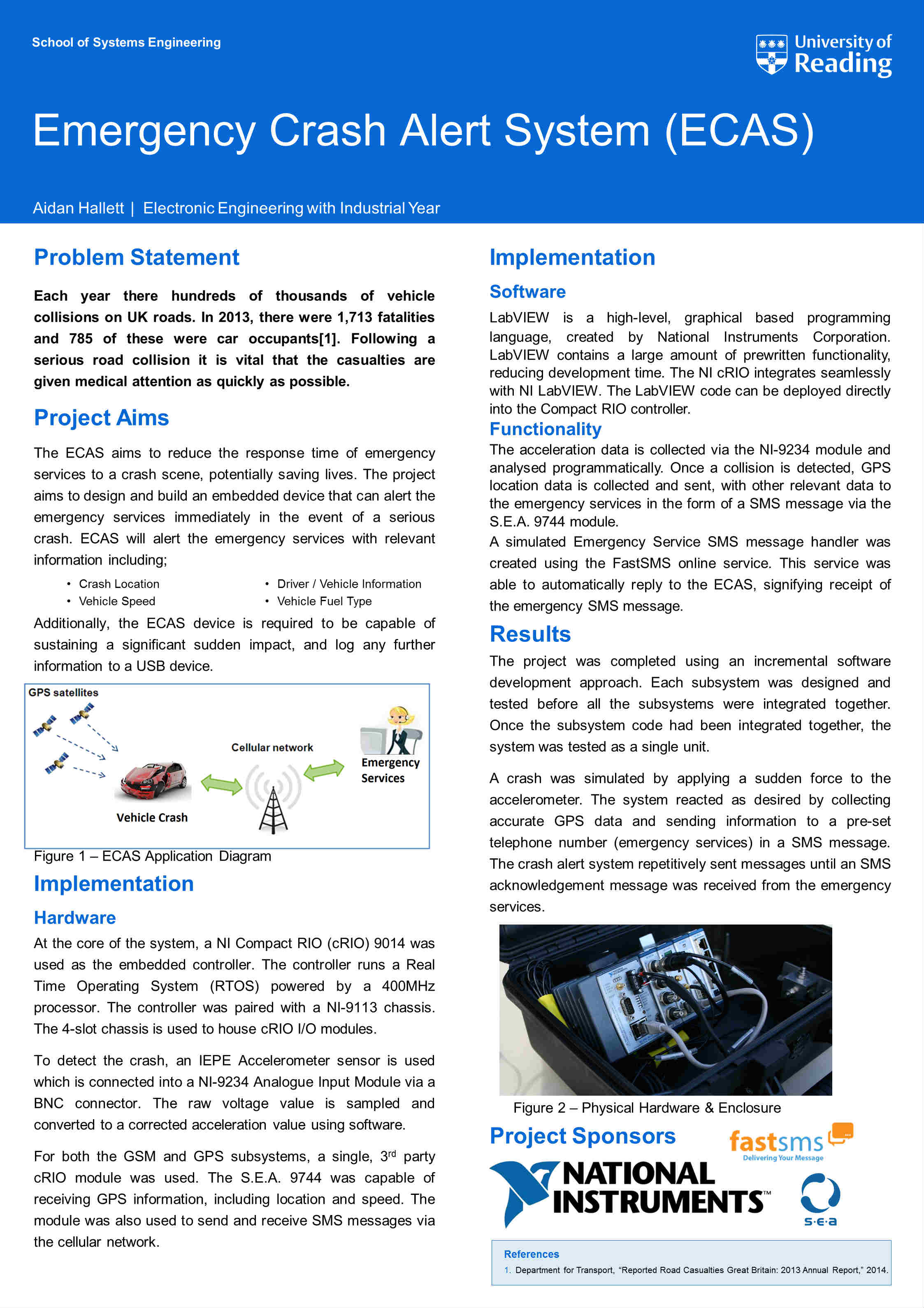
The behaviour of the system can be seen in Figure 1. The ECAS device is used to monitor the acceleration endured by the vehicle. In the event of a simulated collision, the device automatically sends the last known GPS location of the vehicle to the FastSMS using an SMS via the telephone network. An automatic SMS message is then sent to the ECAS from the FastSMS server. The SMS collision data is then accessed using a HTTP API and displayed on a GUI. A detailed system breakdown hierarchy for both the ECAS system and the Control Room can be seen in System_Breakdown.pdf (attached).
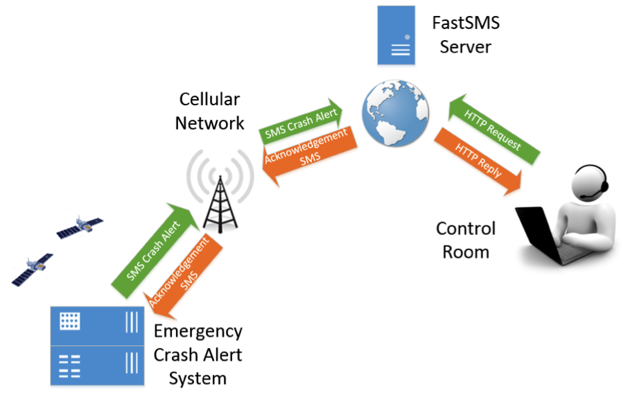 Figure 1 - High Level System Overview
As seen in Figure 1 &System_Breakdown.pdf (Attached), the project can be broken down into two large sections; (1) The ECAS Device itself and (2) The Control Room.
ECAS Behaviour Overview
System Boot & Initialisation
Once powered, the embedded device takes approximately 30 seconds to initialise before the deployed code begins to run. The system then initialises a connection with the GPS network, allowing location information to be gathered.
Data Acquisition
Data is acquired from the accelerometer sensor at 50 samples per second, and GPS location information is acquired at 4 samples per second. Both data is added to a FIFO buffer, coupled with a timestamp of the information.
Logging to File
Before the system can be logged, a file must be created. The location of this file is dependent on whether a USB memory stick is presently inserted into the cRIO. Once a file has been created, data from the front of the buffer is removed from the buffer and logged to file.
Crash Detection & Emergency Message
The acceleration data that is collected from the accelerometer is checked regularly and is used for detecting a collision. Once a crash has been detected, the system connects to the cellular telephone network and attempts to send a message to an external system (FastSMS) containing relevant information such as location, driver information and speed.
Acknowledgement & Shutdown
The ECAS then waits for a pre-set period of time (e.g. 20 seconds) for a SMS message reply from the external system (FastSMS). If no message received in this time, the system attempts to resend the message until an acknowledgement is received by the embedded device. An automatic acknowledgement message is sent from the external system (FastSMS) back to the embedded device upon receipt of an emergency message. Any remaining data logged in the file is then logged to file, before the system shuts down safely.
ECAS Device (Section 1)
Hardware Design
The Compact RIO (cRIO) is the core of the system, communicating with other hardware modules and running the LabVIEW code on the RTOS. An NI-9234 4-channel module was used in conjunction with the PCB IEPE 608A11 accelerometer. The 608A11 single axis accelerometer connects to the accelerometer via a BNC connector.
The GPS and GSM communication systems are a fundamental section of this project. A single C-series module was used to provide both GPS and GSM functionality. The S.E.A. 9744 module slots into the NI-9113 chassis and connects to the cRIO controller using an Ethernet connection. The S.E.A. 9744 module was programmed using NI LabVIEW. Two aerials; a GPS and GSM aerial were connected directly into the NI-9744 module and used as transceivers for the system.
The cRIO accepts a DC power supply from 9-35 volts and the S.E.A. requires its own 7-30V DC supply. A transformer was used to provide the cRIO and S.E.A. module 24V (1.25A) its primary power. A cigarette lighter plug was used to provide the system power (12V DC) when deployed in a vehicle. A power port was mounted on the side of the enclosure, meaning the enclosure could be safely shut when deployed.
A secondary power source was also implemented into the system. Power is sourced from the backup supply (12V DC 3000mAh Lithium-ion rechargeable battery) in the event of failure of the primary source. The cRIO switches to the secondary supply if required.
Software Design
There are three different queues in the solution:
- The Collected Data Queue
- Comprises of two types of information; Acceleration Data & GPS Data. Both types contain an additional timestamp, which is used when writing the information to file. Information is only removed from this queue in the Message Handling Loop (Log Data State or Exit State).
- GPS Acquisition States
- The GPS Acquisition Loop has various states (discussed below), which are added and read from the FIFO GPS Acquisition States buffer.
- Message Handling Loop States
The Message Handling State Queue is used to queue future states of the Message Handling Loop. There are 8 various states that can be added to the queue (discussed below). Queued Messages (states) can be enqueued from two main locations; The Acceleration Loop and the Message Handling Loop. The information is removed from the queue (dequeued) in a single location, at the start of the Message Handling Loop.
In this application there are three different loops; (1) Acceleration Acquisition Loop, (2) GPS Acquisition Loop and (3) Message Handling Loop that all operate at different rates. Information is transferred between the loops using two of the three queues; (1) Collected Data and (2) Message Handling State. Figure 2 shows the communication between the loops.
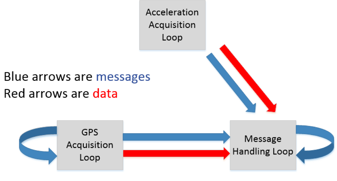
Figure 2 - ECAS Loop Communication
Acceleration Acquisition Loop
The Acceleration Loop is a data acquisition loop, acquiring accelerometer data frequently from a 608A11 accelerometer through the NI-9234 Module. Samples are collected 50 times per second (50Hz). Any accelerometer data collected is converted from a raw voltage reading to a useful acceleration reading measured in G-Force (1g = 9.8m/s^2). This measurement is then added to the Collected Data Queue where it can be written to file in the Message Handling Loop. The Acceleration Loop is also responsible for determining whether a vehicle collision has occurred, and if a crash has occurred; notifying the Message Handling Loop which can respond accordingly.
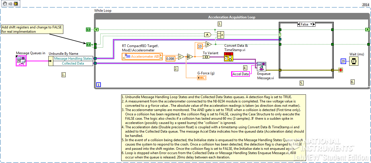
Figure 3 -Acceleration Loop Snippet
GPS Acquisition Loop
The GPS Data Loop is responsible for initialising the connection with the S.E.A. 9744 module, retrieving GPS data from the module and sending the GPS data to the message handling loop via the Collected Data Queue. The GPS Data Loop acts as a state machine, using the GPS Acquisition States Queue to determine the next state. The five various states and possible transitions between the states can be seen in Figure 5.9. Green arrows show normal behaviour of the loop (i.e. No collision occurred). Red arrows show the transitions between the states once a crash is detected and the Message Handling Loop has shut down. Black arrows indicate other state transition possibilities.
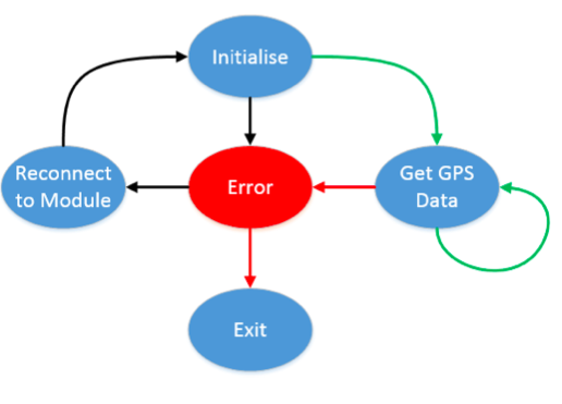
Figure 4 - GPS Loop States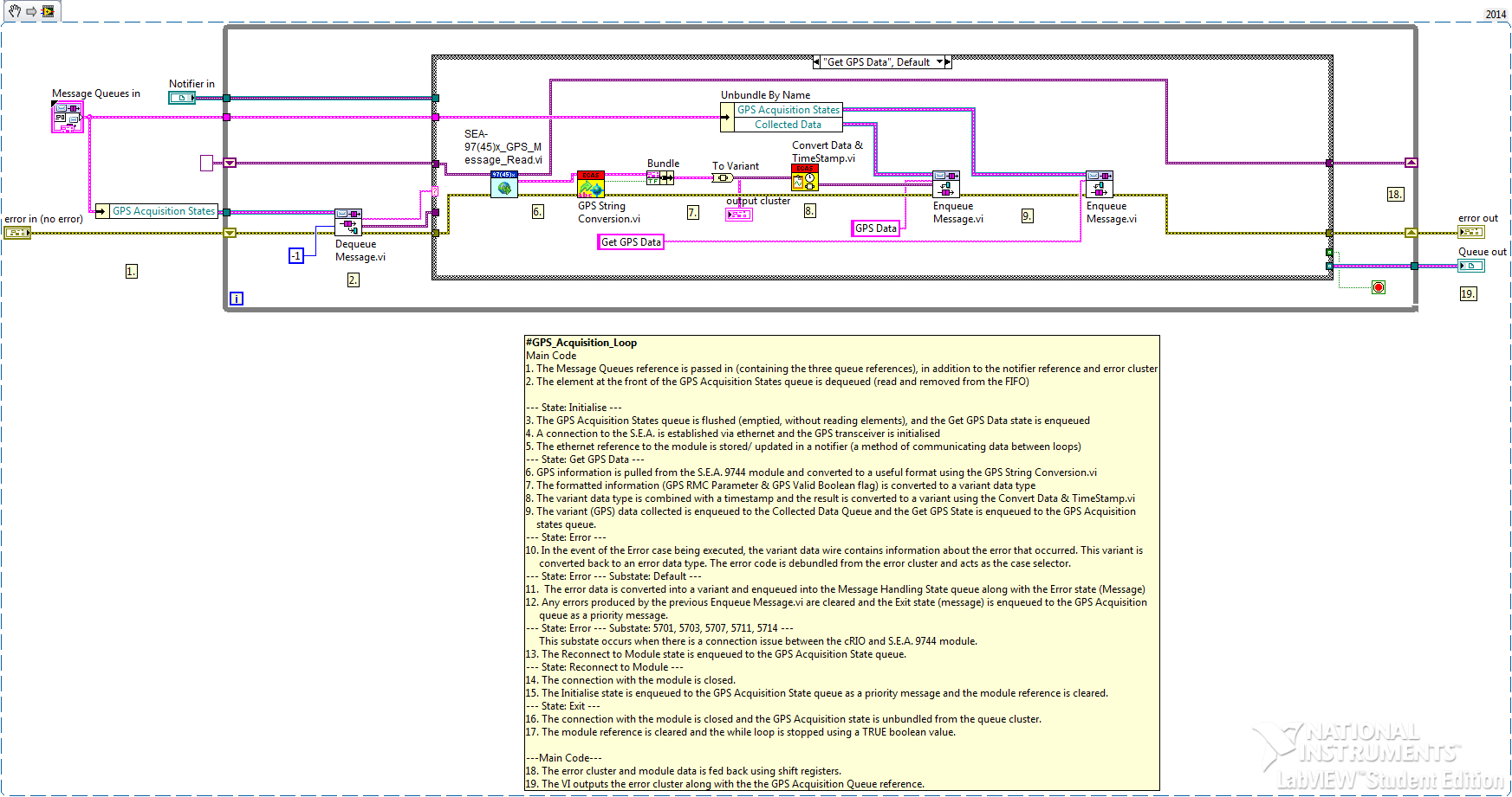 Figure 5 - GPS Acquisition Loop LabVIEW Snippet
Message Handling Loop
The Message Handling Loop is the most important loop. It is used to deal with incoming messages and data from the other two loops (Acceleration Loop and GPS Acquisition Loop). The Message Handling Loop logs information to file and sends an emergency SMS when instructed to do so by the Acceleration Loop. Whilst the Message Handling Loop is much more complex that the other loops, the functionality is broken down into a number of states. The Message Handling Loop acts as a state machine. The various states and transitions can be seen in Figure 5.10. Green arrows represent normal behaviour of the system if no crash has occurred. Red arrows represent the typical state transitional behaviour of the system in the event of a collision. Black arrows represent other possibilities, however are less common.
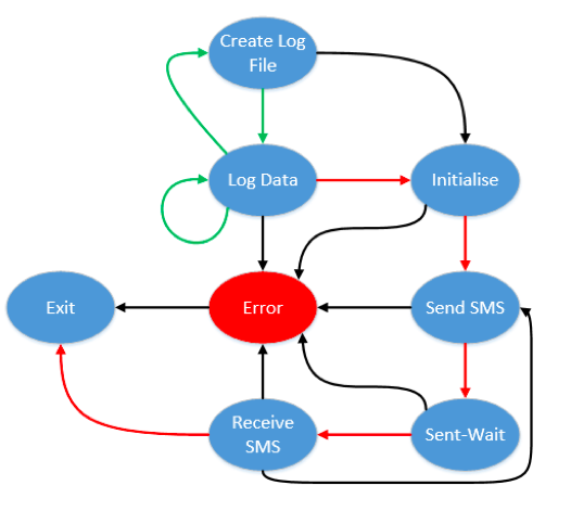
Figure 6 - MHL States

Figure 7 - MHL LabVIEW Snippet

Figure 8 - ECAS Hardware
Control Room (Section 2)
The Control Room application is an additional application used to demonstrate how an entire Emergency Crash Alert System or eCall system may work. The Control Room is used to receive incoming emergency crash alerts from ECAS systems that have been deployed into vehicles. Any SMS message data that is sent through the FastSMS service can be managed easily using this application, which displays vital crash information to the Control Room Operator such as the location, and last known position.
The Control Room was programmed using LabVIEW. Any SMS received by the FastSMS telephone number is stored as string information on the FastSMS server. The Control Room requests the information from the FastSMS servers using a HTTP API. A large amount of the code in this application is used to organise the string data received from the server into a visually clear and simple format.
The Control Room GUI displays tabulated data in addition to a map. In the event of a collision, the table is automatically updated, and the exact location an incident ID is plotted to the map. There is no limit of the number of incidents that the system can handle (and plot correctly).
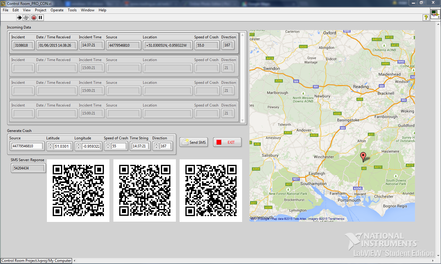
Figure 9 - Control Room Front Panel
Benefits of LabVIEW & NI Tools?
I decided to use NI LabVIEW and NI Hardware for this project for a number of reasons.
Firstly, one of the primary aims of the project was to design and build a rugged embedded system prototype that can sustain substantial sudden forces. In this project, a Compact RIO was used which, by design is tough and durable. Adopting the RIO platform meant that I did not have to spend time strengthening other hardware platforms. The cRIO is reliable embedded hardware that uses a real time operating system. In this project, it was crucial that the emergency services were notified as soon as possible. The Real Time Operating System ensured that device behaved deterministically.
The LabVIEW programming language allowed fast development given the vast array of built in functionality. In this project, it was vital that parallelism was used (to support the three loops). LabVIEW allows this advanced programming technique to be implemented very simply, reducing complexity and saving time.
The Compact RIO supports hundreds of C-Series modules, all with their own signal conditioning circuitry. As I have found, the cRIO also works seamlessly with third party modules such as the S.E.A. 9744 that I have used in this project.
As part of thorough software and system testing, NI LabVIEW Unit Test Framework was used to test a variety of functions. Although I had little experience with this LabVIEW Toolkit, the software is intuitive. I was able to complete Unit Tests in minutes – not hours! The Unit testing directly impacted the quality of the project as a number of software bugs were found quickly and efficiently.
National Instruments hardware and software work seamlessly together saving a huge amount of time which allowed me to drastically increase the quality of the project.
With NI LabVIEW & NI Tools, I easily achieved the initial goals set by my Supervisor & Myself. NI also offer an exceptional level of technical support should there be any issues.
For these reasons, I believe that NI Tools allowed me to create a much high quality project that I would have otherwise be able to do in the set timeframe.
Further Developments & Testing
Whilst the project is fully functional, there are a number of additional (non-essential) features that could be added to the system including;
- Utilize the CAN/ OBD port in a vehicle to extract relevant information from the vehicle (such as throttle position, brake position, VIN data, fuel type, number of passengers in the vehicle (from seatbelt sensors), etc)
- Create a Data Dashboard screen that allowed users to customize the information that was send by the ECAS device in the event of a collision.
Testing
When completing this project, I completed a variety of testing including; Unit Testing (as previously discussed), Drop Testing, Vehicle Acceleration testing and EMC Testing (Provided by TUV SUD). Although numerous companies were contacted regarded Acceleration sled testing (including TRL, Millbrook, Cranfield University), none were able to sponsor the project.
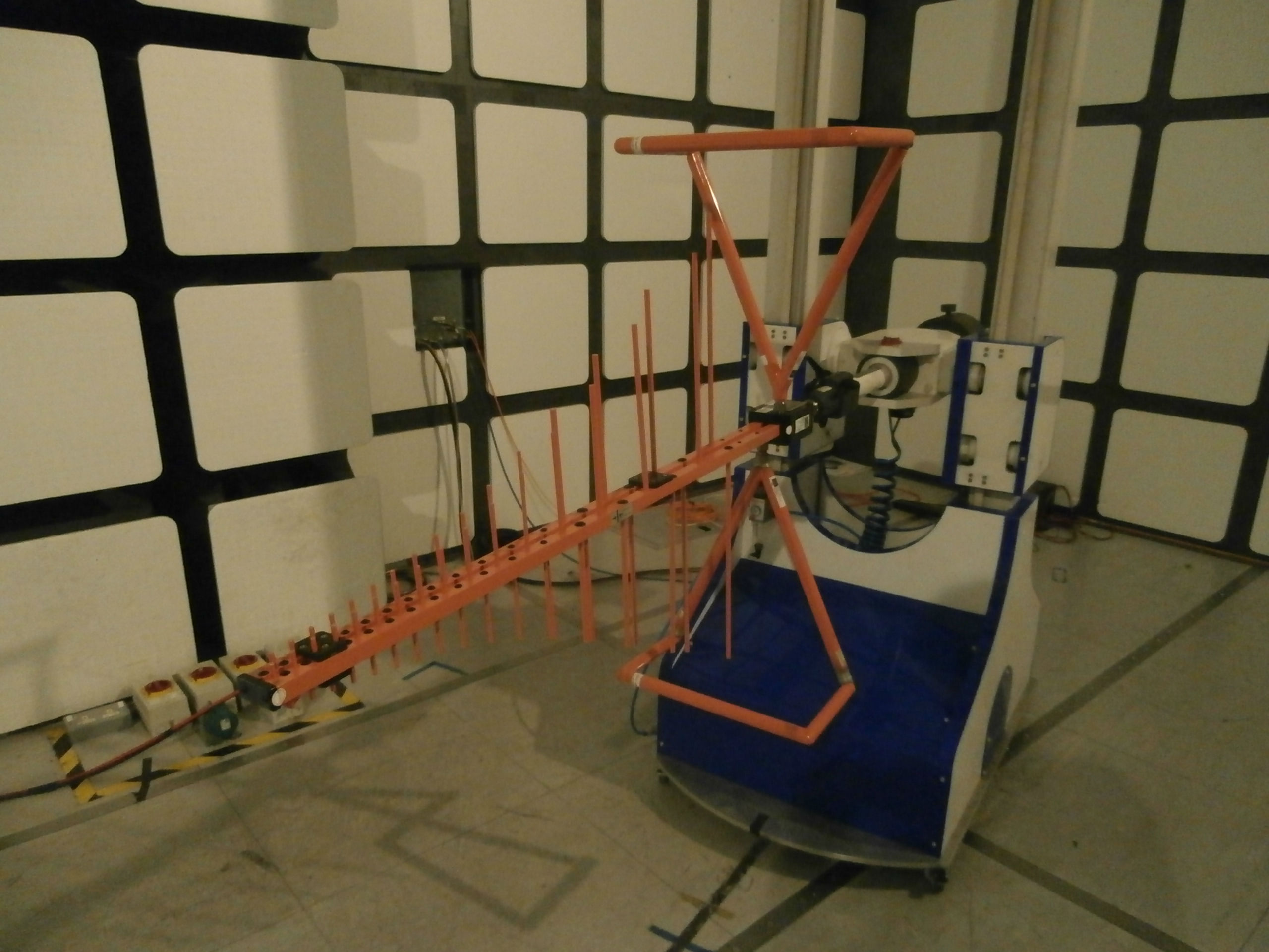
Figure 10 - EMC Testing - Radiated Emissions Detection Hardware
Given more time and a budget for testing, I intend to subject the ECAS device to sled testing.
Anything else?
I have attached a SCARP 4 page summary of the project that was completed one month prior to the completion date.
All uploaded code has been commented thoroughly.
I have also won a local IET competition for my project. I presented to a number of judges whom complimented me on my presentation skills and also the approach to the project. The judges easily saw the need for such a device. I am now through to the next stage of this Global Competition. More information can be found on University of Reading’s website [Link].
Time to build & all project reports & testing: Approximately 5 months.
Poster
Video
- Mark as Read
- Mark as New
- Bookmark
- Permalink
- Report to a Moderator
Awesome work!!
- Mark as Read
- Mark as New
- Bookmark
- Permalink
- Report to a Moderator
Greate work
