- Document History
- Subscribe to RSS Feed
- Mark as New
- Mark as Read
- Bookmark
- Subscribe
- Printer Friendly Page
- Report to a Moderator
- Subscribe to RSS Feed
- Mark as New
- Mark as Read
- Bookmark
- Subscribe
- Printer Friendly Page
- Report to a Moderator
*Visit the official "Submit Entry" page to enter your NI LabVIEW student design project in the competition*
*Please add your country to the title of your project, example: Amazing Robot Project, Poland.
Contact Information
University: Chungbuk University, South Korea
Team Member(s): Sung-Hwan_Lee
Faculty Advisors: Prof. In-Hwan_Lee
Email Address: hanris@hanmir.com
Country: South Korea
Project Information
Title: Micro-Stereolithography System, South Korea
Description:
This application is to control three-axis stage and shutter by using products, which make Micro-Stereolithography System
Products:
NI PXI
NI-7344
NI-6251
MID-7604
LabVIEW 7.1
The Challenge:
In background, MEMS(Micro Electro Mechanical System) is to make prototype which is from micro component. Those are used in a various area. However, it is difficult for this techlogy to make micro structur
es which are high slenderness ratio. Therefor Micro_Stereolithography System is solution.
This project means LabVIEW program makes Micro-Stereolithography System easy to control. In addtion, LabVIEW makes a program easy to make it
The Solution:
1. System construction
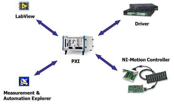
<Figure 1>
This System consists of LabVIEW, motion controller, step motor power drive, analogue feedback.
This software create taget position, trajectory that is from velocity and acceleration based on LabVIEW 7.1. Moreover, present position is displayed by encoder.
Motion controller create trajectory of motor, coordinate of encoder, direction of motor
Driver make volt to be amplified to work ball screw
2. Motion Controller
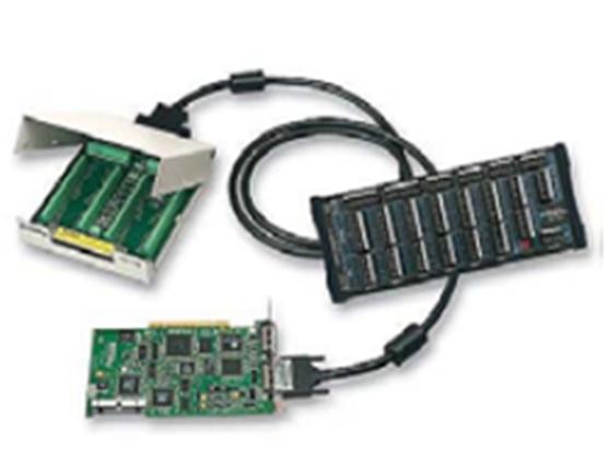
<Figure 2>
NI 7344 controllers offer advanced features such as blended motion trajectory control and fully coordinated circular, linear, point-to-point, gearing, and vector-space control in either embedded motion operation or host-centric programming environments. The CPU and DSP components operate together to optimize closed-loop control, Thus it makes any structure.
3. Step motor power drive
Drive is MID-7604 power drive which is a complete power amplifier and system interface for use with for axes of simultaneous stepper motion control. It simplifies field wiring through separate encoder, limit switch, and motor power removable screw terminal connector blocks for each axis.
4. MAX(Measurement & Automation) 설정
MAX creates values of motor controller and DAQ. Major values are stepper steps per revolution, limit switch, following error and encoder counts per revolution.
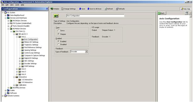
<Figure 3>
Bind type of motor as you see Figure 3
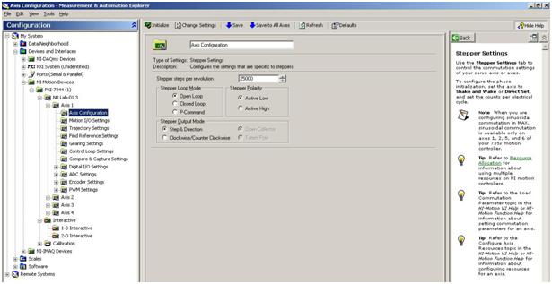
<Figure 4>
Figure 4 express value of stepper step per revolution. Motor has specification of 1.8 deg/s, 1.5A, so it has 200 pulses per revolution. Therefore, value must be 25000 steps
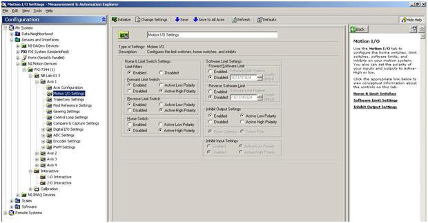
<Figure 5>
In Motion I/O Settings, Limit Switch can be changed. It has function that accidental occurrence are prevented in advance. I have to use this function.

<Figure 6>
Encoder is required to write specification. This encoder has 50nm of resolution, so encoder counts per revolution should be 40000 steps

<Figure 7>
In this Figure, I set up following error. It means error between resolution of motor and encoder. It is set up by difference. If it counts more than values, motor will be stopped

<Figure 8>
3. Front Panel
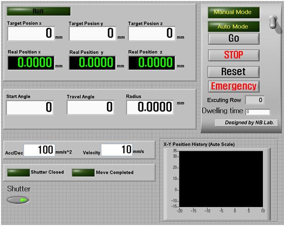
<Figure 9>
This consists of display of encoder and input of commands. Front panel has divided into two-part. First of all, manual mode is to control three-axis stage by manual. I have to put value to use it. As a variable, there are X, Y, Z axis, velocity, acceleration. Second, auto mode is to read memo file. It deals with commands by row.
4. Block Diagram
1) Encoder
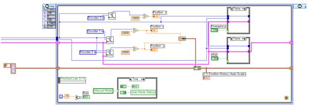
<Figure 10>
In this Figure, values of encoder is displayed. After obtaining steps of encoder, it is divided by resolution, so unit of ‘mm’ is expressed. Also, there is chart for X, Y axis
2) Sutter
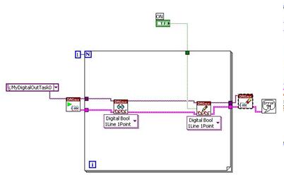
<Figure 11>
This is process to handle DAQ. It’s very simple. After getting information of shutter, it decides.
2) Manual Mode

<Figure 12>
In this figure, this is manual mode penal. This penal is for manual control. I have to change unit from ‘mm’ to step because drive only read unit of step.
3) Auto Mode
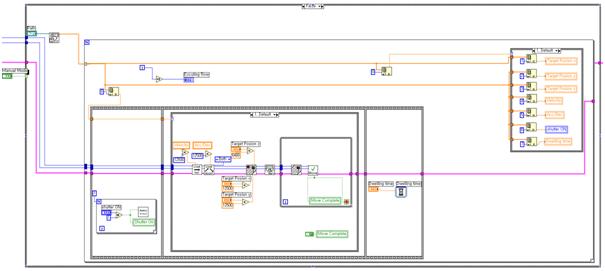
<Figure 13>
First, user has to make memo file for auto mode. And then, it handles command by row. The method is the same as manual mode.
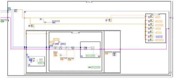
<Figure 14>
In this figure, it is made to control curve from files.
Nominate Your Professor: (optional)
I nominate Prof. In-Hwan_Lee which is mechanical field
He support me to use machine and LabVIEW. He makes a surroundings