From 04:00 PM CDT – 08:00 PM CDT (09:00 PM UTC – 01:00 AM UTC) Tuesday, April 16, ni.com will undergo system upgrades that may result in temporary service interruption.
We appreciate your patience as we improve our online experience.
From 04:00 PM CDT – 08:00 PM CDT (09:00 PM UTC – 01:00 AM UTC) Tuesday, April 16, ni.com will undergo system upgrades that may result in temporary service interruption.
We appreciate your patience as we improve our online experience.
University and Department: Georgia Institute of Technology, Biomedical Engineering
Team Members: Joseph Abrahamson, Sanjay Challa, Shuyen Liu, Ginger Tsai
Faculty Advisors: Dr. Franklin Bost, Dr. John Nickerson
Primary Email Address: sanj1988@gmail.com
Primary Telephone Number: 678-910-0330
Hardware:
Software:
NI LabVIEW, RT, FPGA
Describe the challenge your project is trying to solve.
Our advisor and client, Dr. John Nickerson, is interested in the effect of specific genes on eye development. Specifically, his foucs is on identifying genes which may affect gross eye shape during growth and lead to ophthalmological conditions such as myopia. In order to understand the effect of specific genes, Dr. Nickerson is interested in examining the shape and size of the dissected eyes of genetically modified mice. Our project was thus focused on developing a device capable of measuring the complete 3D external surface of dissected mouse eyeballs and creating a reconstruction the the eyeball at a micron/submicron level of precision.
Describe how you addressed the challenge through your project.
We addressed the challenge of building such a device by making extensive use of the resources available to us. We took the time to understand and experiment with the micrometer that Dr. Nickerson wanted for us to use, in terms of functionality and I/O. We made use of the rapid prototyping devices at our disposal to build and analyze many different frame and harness designs. Lastly, we used the help of our advisors and TAs to motivate improvements to our design. Our final design solution invovles rotating the eye at a constant speed while measuring it with the micrometer. The micrometer is stepped up to a new plane after measuring one full revolution of the spinning eye at a given plane. Data is collected from the micrometer only as it is measuring the eye at a given plane, and not while moving to a higher plane. In this manner, the final device is able to collect a description of the eye in the form of a stack of measured slices of the eye. On the software end, our device uses the data to create a 3D reconstruction of the eye in real-time.
Future Work
The device as completed early May succeeds at the proof-of-concept level but is not sufficiently accurate for our client's application. Further funding was obtained to continue the project by replacing components with high accuracy, high repeatability parts to reach micron-level accuracy of the completed scan while also enabling the package to be easily and cheaply deployed in other ophthalmological research labs. The new project is slated to be functional by late June 2010 and tested/calibrated by end of July 2010.
New Hardware:
Proof-of-concept Device (May 2010)
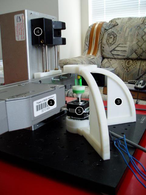
The scanning head setup. Picture shows the 3D printed support frame (3), theta-actuation drive (5), z-actuation shaft (4) and micrometer head (1).
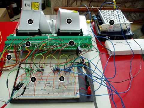
Controller and RT/FPGA setup. A custom built case for an NI sbRIO was built to house and two connector blocks (9) and their cables (10). Also shown are two drive control circuits (8), a ribbon cable input from the micrometer (11), and the drives' power supply (12).
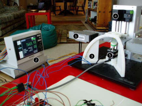
The viewing setup. As with the first picture the operating frame is shown, but this view also displays the micrometer control display (2).
Video of the device in action:
