- Document History
- Subscribe to RSS Feed
- Mark as New
- Mark as Read
- Bookmark
- Subscribe
- Printer Friendly Page
- Report to a Moderator
- Subscribe to RSS Feed
- Mark as New
- Mark as Read
- Bookmark
- Subscribe
- Printer Friendly Page
- Report to a Moderator
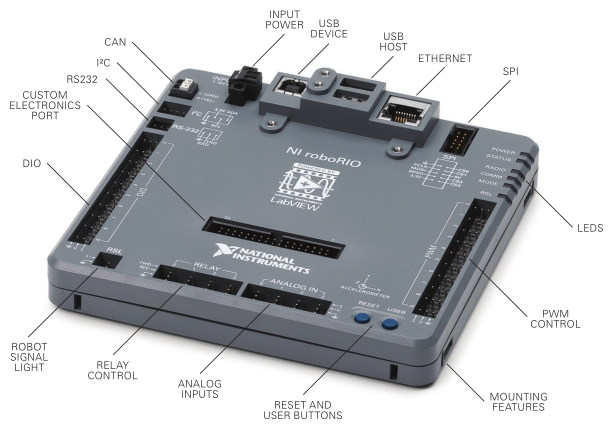
roboRIO Details and Specifications
Introducing the NI roboRIO Advanced Robotics Controller. This rock-solid device was designed specifically with FIRST in mind. It's more powerful, lighter, and smaller than the previous cRIO, giving FRC teams unmatched power and versatility.


F.A.Q.
Does roboRIO support other programming languages?
> Yes, you can program the roboRIO in LabVIEW, Java, and C++. A few teams even use Python, although it's not technically supported.
When can we purchase a spare roboRIO?
> All rookie FRC Teams get a free roboRIO in their Kit of Parts. All FRC teams can purchase additional roboRIOs at an 80% discount off of the retail price from AndyMark here.
How is roboRIO different from cRIO?
> NI roboRIO uses the same basic architecture of a Real-Time processor + FPGA, but the roboRIO is faster due to the processor being dual-core. All of the I/O is accessible direclty on the roboRIO controller, so the cRIO's digitial sidecar is unnecessary. The Real-Time programming architecture you use to program the roboRIO is nearly identical to the way that professionals use LabVIEW to program their cRIO systems.
How is roboRIO different from myRIO?
> Both devices use the Xilinx Zynq chipset (processor + FPGA) and use a lot of the same architecture. roboRIO has connectors and I/O specific for use in FIRST (e.g. CAN and PWM connectors), while the myRIO uses generic screw terminals for all I/O. The software experience will also differ between the devices since the roboRIO will require the FRC Update Suite for use in FIRST Robotics Competition. Additionally, the roboRIO is designed to be more rugged than the myRIO so that it can survive multiple FRC seasons through features such as conformal coating and extra short protection.
What operating system does roboRIO Use?
> NI roboRIO will be running the NI Linux Real-Time OS which is used is most of NI's new RIO devices. Introduction to NI Linux Real-Time, Under the Hood of NI Linux Real-Time
Can I use a Linux computer to program the roboRIO?
> No. You will still need to use a Windows computer to program and control the roboRIO, as the roboRIO tool chain is only supported in Windows.
Can non-FRC Teams purchase a roboRIO?
> Yes. Industry professionals and university students can purchase the roboRIO directly from National Instruments here. FRC teams, affiliates, partners, and organizers can purchase roboRIO from AndyMark provided they will be used to support FRC teams and competitions.
Custom Electronics Port (MXP)
Create your own custom electronics board for any extra inputs and outputs for your system. Check out the MXP Developers Guide for more information on how you can deisgn your own MXP board.
! Idea: Have an awesome idea for a custom Expansion Board that would be useful for many teams? Create one and use tools like Kickstarter to share your work with other teams!
roboRIO MXP Pinouts

- Mark as Read
- Mark as New
- Bookmark
- Permalink
- Report to a Moderator
jvedder wrote:
The Xilinx Zynq has a few errata regarding the I2C and SPI ports. Most notably are these three:
Missing I2C Master Completion Interrupt
http://www.xilinx.com/support/answers/61665.html
I2C Master Generates Invalid Read Transactions
http://www.xilinx.com/support/answers/61664.html
SPI RxFIFO Not Empty Status is not Updated Promptly
http://www.xilinx.com/support/answers/47575.html
Does the roboRIO include workarounds for these?
Thanks,
John
The first I2C errata is worked around because the driver will not issue a repeased start to a different address.
The second I2C errata can be worked around by the user not reading more than 255 bytes at a time from a device.
The SPI work-around is not included.
- Mark as Read
- Mark as New
- Bookmark
- Permalink
- Report to a Moderator
What version of c++ will the development environment support? C++11?
- Mark as Read
- Mark as New
- Bookmark
- Permalink
- Report to a Moderator
Does the CAN bus offer a ground connection?
http://www.oxts.com/faq/how-do-i-connect-my-can-bus/
What is the proper CAN wiring for the Jaguars? Wire colors have different meanings in the Jaguar docs (page 24 in this doc)
http://content.vexrobotics.com/docs/217-3367-VEXpro_Jaguar_GettingStartedGuide.pdf
- Mark as Read
- Mark as New
- Bookmark
- Permalink
- Report to a Moderator
dano13 wrote:
What version of c++ will the development environment support? C++11?
NI has shipped tools compatible with the roboRIO that include gcc 4.7. WPI is working on shipping tools that will be used by FRC teams that include gcc 4.9.
- Mark as Read
- Mark as New
- Bookmark
- Permalink
- Report to a Moderator
devodl wrote:
Does the CAN bus offer a ground connection?
http://www.oxts.com/faq/how-do-i-connect-my-can-bus/
What is the proper CAN wiring for the Jaguars? Wire colors have different meanings in the Jaguar docs (page 24 in this doc)
http://content.vexrobotics.com/docs/217-3367-VEXpro_Jaguar_GettingStartedGuide.p df
The FRC system does not provide ground connections for the CAN connections. This would create ground loops. All you want or need is the 2 differential CAN bus wires.
The colors of wires are not the important thing to take from that document, since some cables have different colors... the key is to correctly wire the CAN H and CAN L wires to the roboRIO and PDP. On the roboRIO and PDP, the CAN H is yellow and the CAN L is green. On the Jag, pin 2 (commonly red) is CAN H and pin 3 (commonly green) is CAN L. Just make sure you wire CAN H to CAN H and CAN L to CAN L and you should be fine.
roboRIO includes a terminator. The PDP also includes an optional terminator that defaults to enabled. If you wire all of your devices in between those two devices then that should take care of the termination requirements.
- Mark as Read
- Mark as New
- Bookmark
- Permalink
- Report to a Moderator
Thanks for the explanation.
DAQjr wrote:
roboRIO includes a terminator. The PDP also includes an optional terminator that defaults to enabled. If you wire all of your devices in between those two devices then that should take care of the termination requirements.
So then the CAN bus would start at the roboRIO daisy chain through the devices and terminate at the PDP?
What is the purpose of the roboRIO including a terminator? For when nothing is connected?
- Mark as Read
- Mark as New
- Bookmark
- Permalink
- Report to a Moderator
devodl wrote:
So then the CAN bus would start at the roboRIO daisy chain through the devices and terminate at the PDP?
Yes
devodl wrote:
What is the purpose of the roboRIO including a terminator? For when nothing is connected?
No... It is there so that you only have to concern yourself with one additional terminator. We assume that you will only ever have one roboRIO on the CAN bus, so it makes sense to have the roboRIO at one end and therefore include a terminator.
- Mark as Read
- Mark as New
- Bookmark
- Permalink
- Report to a Moderator
How would a 12v sensor, such as a prox switch, be wired?
- Mark as Read
- Mark as New
- Bookmark
- Permalink
- Report to a Moderator
Hi: Our team has to wait a month or more to get parts.
I would like to get a head start on ordering the connectors needed for the RoboRIO.
Can you provide a list with part numbers?
I can't tell from the picture, do I need a CAN bus connector or are the wires held by the RoboRIO?
D
- Mark as Read
- Mark as New
- Bookmark
- Permalink
- Report to a Moderator
@Dee2 I have added a table of common MXP part numbers on the roboRIO MXP Dev Guide page, It looks like the MXP header is a non-stock part for digikey, but I am working with them to try to get some in stock so teams can get them asap.
Cheers
Hunter
- Mark as Read
- Mark as New
- Bookmark
- Permalink
- Report to a Moderator
For CAN, the wires are held by the roboRIO.
One other note, the PDP has a cover that covers the battery wire connections. Many connectors that we had did not fit. However, the connectors sold by AndyMark and Cross The Road Electronics do fit.
- Mark as Read
- Mark as New
- Bookmark
- Permalink
- Report to a Moderator
I see that windows is still required to program the Robo Rio.
Are there any plans to improve on this ?
We are finding that even our fastest Laptops seem slow and hoping that a slimmer OS (LINUX) will work better for us now that the LINUX RT is available..
Can I use a Linux computer to program roboRIO?
You will still need to use a Windows computer to program and control the roboRIO as the roboRIO tool chain is only supported in Windows.
Tx, Charlie Affel, Mentor FRC 423
- Mark as Read
- Mark as New
- Bookmark
- Permalink
- Report to a Moderator
caffel wrote:
I see that windows is still required to program the Robo Rio.
Are there any plans to improve on this ?
We are finding that even our fastest Laptops seem slow and hoping that a slimmer OS (LINUX) will work better for us now that the LINUX RT is available..
Can I use a Linux computer to program roboRIO?
You will still need to use a Windows computer to program and control the roboRIO as the roboRIO tool chain is only supported in Windows.
Tx, Charlie Affel, Mentor FRC 423
I believe you will be able to use Linux if you program in C++ or Java. LabVIEW only supports targeting RT targets from windows. You will also need a Windows computer to run the imaging tool, but that is needed infrequently.
- Mark as Read
- Mark as New
- Bookmark
- Permalink
- Report to a Moderator
I'd like to help program and possibly debug (but not necessarily run) LabView under Linux.
Has FRC got a licence that covers the Linux version.?
Thanks.
Chris Lynch, Mentor FRC 423
- Mark as Read
- Mark as New
- Bookmark
- Permalink
- Report to a Moderator
TopSailChris wrote:
I'd like to help program and possibly debug (but not necessarily run) LabView under Linux.
Has FRC got a licence that covers the Linux version.?
I've heard of teams being given a license for LabVIEW for Linux when requested. It only runs on the x86 / x64 Linux desktops. It does not include the RT module (since it doesn't exist for Linux) which means you couldn't edit or deploy robot code from the Linux version.
- Mark as Read
- Mark as New
- Bookmark
- Permalink
- Report to a Moderator
Our team bought a second RoboRIO for development work with the camera and a separate Arduino module. Is it OK to pwer the RoboRIO from a seaparate power supply, or do we need to get another Power Distribution Panel also?
- Mark as Read
- Mark as New
- Bookmark
- Permalink
- Report to a Moderator
For competition, you can only have one power supply which is the lead acid battery. There can be no other source for power. For non competition, feel free to test and use a power supply with proper voltage and amperage. You can't have two RoboRIO's on a robot during a competition, if your camera requires much more computer power than the RoboRIO can handle, you will need to use a small laptop, but the RoboRIO should be able to handle it. Also, I don't recommend using a external 3rd party sorce for power when testing. And finally, for questions regrauding rules, you have to ask on FIRST Q/A forum.
- Mark as Read
- Mark as New
- Bookmark
- Permalink
- Report to a Moderator
Thanks for the quick, helpful response! We really are just doing some software prototyping separate from the robot construction to stay productive.
- Mark as Read
- Mark as New
- Bookmark
- Permalink
- Report to a Moderator
On page 15 of the RoboRio User Manual, figures 16 and 18 show contradictory information about pull-up/down resistors for the DIO ports. Figure 16 shows a pull-up resistor, and figure 18 shows a pull-down resistor.
- Mark as Read
- Mark as New
- Bookmark
- Permalink
- Report to a Moderator
We are unable to update the required firmware version posted on the inspection sheet. For some reason our login and or password or both has been changed not allowing us to have permission for firmware updates. We have tried the default "admin" with blank password and "FRC" / "FRC" to login. Does anyone know a back door to the login or away reset the RoboRio back to system default some we can re-image it?
- Mark as Read
- Mark as New
- Bookmark
- Permalink
- Report to a Moderator
To reset the password, you'll need to call in to support to get some help. They'll be open from 1-7CST today and tomorrow. The number is 866-511-6285.
In preparation, you'll want to get a small thumbdrive and format it to FAT32.
Generally, these kinds of questions are best suited for the FRC Forums found here: https://decibel.ni.com/content/community/academic/student_competitions/frc?view=discussions
- Mark as Read
- Mark as New
- Bookmark
- Permalink
- Report to a Moderator
I have discovered at least three disservices that NI is doing to the community so far (which is pretty bad, considering I've just started as a programming mentor last month):
1) withholding critical information from the specifications. There is no mention of pullup resistors on the digital or I2C (or probably any other) ports in the specifications. We built limit switches to plug into DIO based on the specifications, and they didn't work - because we used pulldown resistors with too low a resistance to allow the pullups to function. Thank God for Chief Delphi. How were we supposed to know - the specifications are supposed to be the authoritative source. But oh - it's in the user's manual, which is supposed to be a non-authoritative source. What sense does that make??
2) Either duplicating names between the MXP and the main ports, or falsely marketing the MXP as providing all these extra capabilities . Is DIO0 on the main board the same as DIO0 on the MXP, or are they two different things? From some subtle clues in the User's Manual, I'm pretty sure it's the latter, but I won't really know for sure until I get in there and try, will I? Yes, the Analog ports on the MXP also repeat port numbers, and PWM, and SPI and I2C. What sense does that make?? Is this an expansion port, or a duplication port? If it really is an expansion port, it will screw up any conceivable library built on it.
I'm also frankly mystified as to why the DIO ports should be 3.3V on output but 5.0V on input. While it does allow use of 5V active sensors, it makes use of 3.3V active sensors problematic. While I can't be entirely sure, it appears that the RoboRIO has blown out two of our 5V KoP gyroscopes in as many weeks. At the risk of sounding redundant, What sense does that make??
Actually, I have read about a last-minute change to the I2C documentation, but I won't actually try to figure that out until Monday. Frankly, at this point I expect things to make anything but sense at the end of the day.
- Mark as Read
- Mark as New
- Bookmark
- Permalink
- Report to a Moderator
http://www.allaboutcircuits.com/textbook/digital/chpt-3/logic-signal-voltage-levels/
The key takeaway from this is that anything higher than 2V is read as a high using TTL logic. The most common implementations are 3.3V and 5V. For an output, you want to choose one of the two. For an input, choosing 3.3V means you'll only be compatible with 3.3V devices. If you choose 5V, you're compatible with any device using either 3.3V or 5V logic. It "doesn't make sense" to complain they give you an input tolerance that will work with more devices rather than being restrictive so the number matches the output voltage. 3.3V will always be greater than 2V. This is true for any device you'll interface with.
- Mark as Read
- Mark as New
- Bookmark
- Permalink
- Report to a Moderator
Wow. Eight months, and I finally get a response, and I don't even
recognize it as being a problem I ever had, and something that might
have made sense if it were documented. I stand by my main, unaddressed,
point - NI's documentation leaves much to be desired.
- Mark as Read
- Mark as New
- Bookmark
- Permalink
- Report to a Moderator
Generally, when you use an excessively aggressive tone, you won't get much of a reply here. Nobody wants to fight with you. And, as we've just witnessed, replying with something rational won't make you any happier either.
You won't find the reasoning I just gave you in any documentation. The values are given to you so that you can make use of them. If you don't understand why the decisions were made, you can research further. It's common practice and something you'll want to get used to if it frustrates you. It made sense without the spec sheets turning into a small research paper.
This is the last reply you'll see from me. If you'd like a conversation, you're more than welcome to send a message to my inbox and I'll do my best to help with whatever I can, although it may be limited. Good luck with the upcoming season.
- Mark as Read
- Mark as New
- Bookmark
- Permalink
- Report to a Moderator
For the record, I wasn't so much angered as disappointed (at least as I
recall it now), though I can see how it came across as anger. I *remain
*disappointed in NI. I know firsthand that NI is (or at least was)
capable of producing excellent hardware, software, and documentation;
I've used their software and hardware professionally to program both
active and passive acoustic data collection and processing systems,
which have somewhat higher demands in both speed and resolution than
FRC, but lower in speed than their RF customers. The only issue I'd had
with NI prior to this January was getting them to take my (agency's)
money; their online documentation was always better than I expected or
needed. I was not directly involved in FRC programming during the cRIO
years; I mentored mechanical and controls (wiring and pneumatics) in
those years. When I did a year as a programming mentor, I frankly
expected NI documentation to be good (or perhaps excellent), and found
it far below acceptable.
I shall have to ask my colleagues who still work with NI to determine
whether the company has lost the bubble, or just doesn't care about FRC.
GeeTwo
- Mark as Read
- Mark as New
- Bookmark
- Permalink
- Report to a Moderator
Are mating connectors available for the PWM, DIO, Relay and Analog In ports? Not the three pin connectors. Can you provide manufacturer, brand, make, model, and part number for the connectors? This information should be in the RoboRIO specification sheet. In industry every piece of hardware comes with a complete interface control document that specifies the details of every signal entering or exiting a box. FRC is supposed to be a realistic engineering environment; in the real world you would be required to provide an ICD.
I want the information for one single connector and one single backshell that simultaneously covers PWM0 to PWM9.
Similarly, one single connector and one single backshell that simultaneously covers DIO0 to DIO9.
And one single connector that simultaneously covers Relay0 to Relay3.
And one single connector that covers Analog0 to Analog3.
And one single connector that covers SPI pins 0 to 9.
Thank you.
- Mark as Read
- Mark as New
- Bookmark
- Permalink
- Report to a Moderator
I have a quick design for IO on the roboRio, that allows the use of latching connectors in place of the standard 3 pin headers. (https://oshpark.com/shared_projects/JN8C1DU5). The board has all the power tied in a bus, and all the ground tied in a bus. Is such a configuration safe for the DIO and PWM ports? Or does each individual connector have its own fuse for the power line?
Thanks!
- Mark as Read
- Mark as New
- Bookmark
- Permalink
- Report to a Moderator
I do not really know the internals very well, but my understanding is
that all the Vcc pins on the PWM ports are the same electrical point,
and all the Vcc pins on the DIO ports are the same electrical point, but
they are not the same point as each other. The PWM provides 6V for
servos, and the DIO and Analog I/O provide 5V for sensors. There is a
blue box in the game rules below R29 this year that indicates that all
of the PWM ports' voltage pins are on the same circuit:
For servos, note that the roboRIO is limited to a max current output
of 2.2A on the 6V rail (12.4W of electrical input power). Teams should
make sure that their total servo power usage remains below this limit at
all times.
Gus "GeeTwo" Michel II
- Mark as Read
- Mark as New
- Bookmark
- Permalink
- Report to a Moderator
There are 3 independent power rails. 3.3V, 5V, and 6V. They are clearly separate from each other. There is no additional separation at the connector level. This includes the SPI and I2C ports' power connections. The exception is the USB 5V Vbus. This is not related or connected to the 5V used for DIO and Analog.
- « Previous
-
- 1
- 2
- Next »
