Transfer multiple channels of data through one DMA FIFO on FPGA
- Subscribe to RSS Feed
- Mark as New
- Mark as Read
- Bookmark
- Subscribe
- Printer Friendly Page
- Report to a Moderator
Products and Environment
This section reflects the products and operating system used to create the example.To download NI software, including the products shown below, visit ni.com/downloads.
- CompactRIO/SingleboardRIO
Hardware
- LabVIEW Real-Time Module
- LabVIEW
Software
- NI RIO
Driver
Code and Documents
Attachment
Description
Description-Separate-1Overview
Currently all NI compactRIO and R series targets have a limit of 3 DMA FIFOs to use for data transfer. If you use the Scan Engine on the cRIO, it will take up 2 DMA channels and only one will be available for use. However, you can still transfer multiple channels of data through one DMA FIFO using interleaving on FPGA and then decimating the array on the host.
Description
The following example shows how to transfer 3 channels of data from a 9205 module on the cRIO through one target-to-host DMA FIFO.
Requirements
LabVIEW 8.6 "or compatible"
LabVIEW 8.6 Real Time "or compatible"
LabVIEW 8.6 FPGA "or compatible"
NI-RIO 3.0 "or compatible"
Steps to Complete
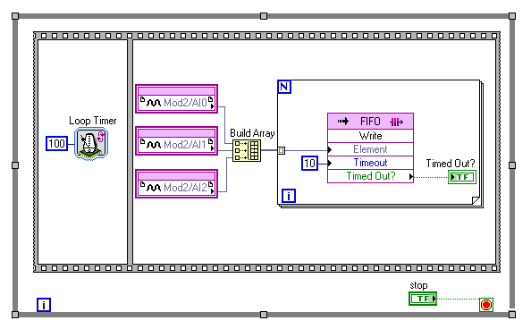
On the FPGA target, we want to build an array of values from the channels we want to send over to the host. Then we feed this array to the FIFO Write function in a For Loop to sequentially write these values to the FIFO:
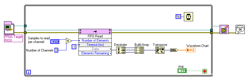
On the host side, we want to read out a number samples that is a multiple of the number of channels of data (so that we read an equal number of samples per each channel). Then we use the Decimate Array function to create an array of values for each original channel. In order to display this data on a Waveform Chart, we build a 2D array and transpose it in order to view the data correctly:
Additional Notes
Note that this architecture involves polling on the host side, so that the host VI will not be able to perform any other functions while waiting. You can modify this architecture to utilize interrupts. For more information, see the interrupt example in the Example Finder (Hardware input and output > compactRIO (or R Series) > FPGA Fundamentals > Host synchronization > interrupt method
**This document has been updated to meet the current required format for the NI Code Exchange.**
Description-Separate-2Example code from the Example Code Exchange in the NI Community is licensed with the MIT license.
- Mark as Read
- Mark as New
- Bookmark
- Permalink
- Report to a Moderator
Informative!!!
- Mark as Read
- Mark as New
- Bookmark
- Permalink
- Report to a Moderator
What is to stop the elements of the array becoming disordered when transmitted over the FIFO? Does the FIFO.Read method automatically sync to the first element of an array, or is it more of a dumb U32 in, U32 out FIFO?
- Mark as Read
- Mark as New
- Bookmark
- Permalink
- Report to a Moderator
Interleaving is nice - but what is a good practice to use more then one cModule for example: 9234, 9222, 9208 wich means: Sigma Delta, SAR with user-controlled I/O and SAR "native" with different Rates (51,2kS, 500kS and 500Hz)?
- Mark as Read
- Mark as New
- Bookmark
- Permalink
- Report to a Moderator
Because of the difference in sampling rates, you can have a separate DMA FIFO for each of those modules. The only hard constraint is that you only have 3 DMA channels to work with, which means you can have a max of 3 FIFOs. This becomes especially difficult when you need one of those to communicate from RT to FPGA as well...
- Mark as Read
- Mark as New
- Bookmark
- Permalink
- Report to a Moderator
Thats the Problem. I try to use 3 (+1 User Mode I/O) while loops, put data in target fifos and then read the data of these fifos in a 5'th loop, finally write it to the target to host fifo - try worth or isn't?
- Mark as Read
- Mark as New
- Bookmark
- Permalink
- Report to a Moderator
I'd say this is worth a try, as long as you have some sort of logic and can tell which samples came from which module. If you have more questions, I encourage you to post them on our discussion forum boards. There's one specifically for FPGA issues. Good luck!
- Mark as Read
- Mark as New
- Bookmark
- Permalink
- Report to a Moderator
Thank you for the example. Is the transpose block redundant? There is an example for NI 9223, "NI 9223 User-Controlled IO Sampling". It doesn't have the transpose block. I haven't run those codes myself. Just curious about it.
- Mark as Read
- Mark as New
- Bookmark
- Permalink
- Report to a Moderator
hello, I would like to transfer multi analog signal (50 Hz) from FPGA to real time LabVIEW.
I run the example Transferring Multi-Channel Data in DMA Applications (FPGA Module),
however, I cannot see any signal at the front panel.
how can I determine samples to read per channel and loop time? or is there any example?
