RFSG Playback Library : Generate 802.11 MIMO Waveform from File (Multiple RFSG)
- Subscribe to RSS Feed
- Mark as New
- Mark as Read
- Bookmark
- Subscribe
- Printer Friendly Page
- Report to a Moderator
Products and Environment
This section reflects the products and operating system used to create the example.To download NI software, including the products shown below, visit ni.com/downloads.
- PXI|VXI
- RF|Wireless
Hardware
- LabVIEW
Software
Code and Documents
Attachment
Overview
This example demonstrates how to use how to do WLAN MIMO Generation by reading waveforms from a TDMS file using the NI RFSG Playback Library.
Description
This example demonstrates how to perform WLAN MIMO Waveform Generation along with Multiple Device Synchronization. It draws reference from the Synchronization using NI-RFSA & NI-RFSG & Synchronizing Sample Clock and Sampled Reference Clock Signals from the NI RF VST Help
Synchronization Using NI-RFSA and NI-RFSG
The NI 5645R allows for multidevice synchronization with Sample Clock-level alignment. To perform multidevice synchronization, you must lock all devices to phase-aligned Reference Clocks. One way to do this is to specify PXI_CLK10 as the Reference Clock source for all devices. If you want to supply an external Reference Clock, some chassis allow you to override the PXI_CLK10 using an external reference input terminal on the chassis.
Alternatively, you can split the external Reference Clock with a passive power-divider or active distribution amplifier and provide a phase-aligned version to each NI 5645R REF IN front panel connector. Refer to the NI PXIe-5645R Specifications document for details about the minimum and maximum levels allowed by the NI 5645R REF IN front panel connector.
The NI 5645R supports synchronization using low-level properties and attributes instead of supporting NI-TClk synchronization. Use the following NI-RFSA and NI-RFSG properties and attributes to synchronize the NI 5645R with another NI 5645R or to synchronize the generator and analyzer on one NI 5645R device.
For repeatable phase offsets between multiple RF channels, share the LO between channels. These channels could be RF IN or RF OUT channels on multiple devices or on a single device. For example, to synchronize two analyzers in NI-RFSA or two generators in NI-RFSG, complete the following steps:
• NI-RFSA
1. Set the LO Export Enabled property or NIRFSA_ATTR_LO_EXPORT_ENABLED attribute to TRUE for one analyzer.
2. Set the LO Source property or NIRFSA_ATTR_LO_SOURCE attribute to LO_In on the other analyzer.
3. Set the LO Frequency property or NIRFSA_ATTR_LO_FREQUENCY attribute to the frequency of the LO signal you are providing to the device.
• NI-RFSG
1. Set the LO Out Enabled property or NIRFSG_ATTR_LO_OUT_ENABLED attribute to TRUE for one generator.
2. Set the LO Source property or NIRFSG_ATTR_LO_SOURCE attribute to LO_In on the other generator.
3. Set the Upconverter Center Frequency (Hz) property or NIRFSG_ATTR_UPCONVERTER_CENTER_FREQUENCY attribute to the frequency of the LO signal you are providing to the device.
If your I/Q carrier frequency is below 375 MHz, you must provide an LO signal to the LO IN terminal that is twice your I/Q carrier frequency and write this value to the niRFSA LO Frequency property or the NIRFSA_ATTR_LO_FREQUENCY attribute.
Synchronizing Sample Clock and Sampled Reference Clock Signals
When you lock all NI 5645R devices to phase-aligned Reference Clocks, the Sample Clocks on all modules are phase aligned. However, the Sample Clocks and Sampled Reference Clocks on all NI 5645R devices are not yet synchronized.
The following table provides information on NI-RFSA and NI-RFSG trigger types and their respective sync trigger master properties, sync trigger dist, and digital edge source property values.
For example, the following steps use the previous procedure to synchronize the Sample Clocks and Sampled Reference Clocks of multiple NI 5645R devices using the Start Trigger and the PXI_Trig0 and PXI_Trig1 external trigger lines. Complete the following steps to synchronize the Sample Clocks and Sampled Reference Clocks of multiple NI 5645R devices using NI-RFSA and NI-RFSG.
1. Set the Reference Clock source to PXI_CLK or RefIn on all devices based on your application.
2. Determine whether to use one or more of the Start, Reference, Advance, or Script trigger types based on your application.
3. Set the sync trigger master to True, and the sync trigger dist line to an available trigger line on the master device. Use the sync trigger master and sync trigger dist line that correspond to the trigger type.
4. Complete the following steps for all slave devices:
- Set the trigger type determined in step 2 to Digital Edge, and set the corresponding digital edge source value, as shown in the previous table.
- Set the sync trigger master to False, and set the sync trigger dist line to the same trigger line that was used in step
- Refer to the previous table to determine which sync trigger master and sync trigger dist line to use.
- Commit the master device.
- Commit all slave devices.
- Initiate all slave devices.
- Initiate the master device.
1. Set the Reference Clock source to PXI_CLK or RefIn on all devices based on your application.
2. Set the Sync Start Trigger Master to True, and set the Sync Start Trigger Dist Line to PXI_Trig0 on the master device.
3. Complete the following steps for all slave devices:
- Set the Start Trigger to Digital Edge, and set the Start Trigger Digital Edge Source to Sync_Start.
- Set the Sync Start Trigger Master to False, and set the Sync Start Trigger Dist Line to PXI_Trig0.
- Commit the master device.
- Commit all slave devices.
- Initiate all slave devices.
- Initiate the master device.
Requirements
Software
LabVIEW 2015 or compatible
Microsoft Visual Studio 2010 SP1 or later
NI-WLAN 15.0
NI-RFSG Playback Library 2.1
NI-RFSG 15.0 or later
NI-RFSG .NET Class Library 15.0*
* NI-RFSG .NET Class Library 15.0 is required only for .NET support.
Hardware
NI PXIe-5673
NI PXIe-5673E
NI PXIe-5644R
NI PXIe-5645R
NI PXIe-5646R
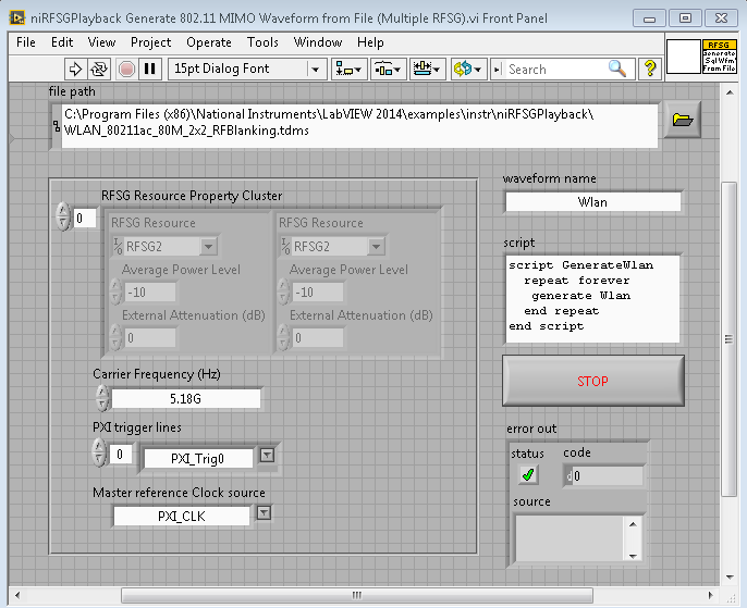
Steps to Implement or Execute Code
1. Configure RF hardware settings (HW Resource Name, carrier frequency, reference level, etc.)
2. Set up the PXI Trigger Lines for VSTs
3. Select the WLAN MIMO TDMS Waveform using file path control and Run the VI
Additional Information or References
Example code from the Example Code Exchange in the NI Community is licensed with the MIT license.
