From Friday, April 19th (11:00 PM CDT) through Saturday, April 20th (2:00 PM CDT), 2024, ni.com will undergo system upgrades that may result in temporary service interruption.

We appreciate your patience as we improve our online experience.

Example Code

Analog Acquisition with Software Analog Reference Trigger

Products and Environment

This section reflects the products and operating system used to create the example.

To download NI software, including the products shown below, visit ni.com/downloads.

    Hardware

  • Data Acquisition (DAQ)

    Software

  • LabVIEW

    Driver

  • NI DAQmx

Code and Documents

Attachment

Overview
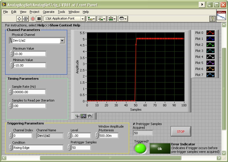
This example demonstrates how to perform an analog software retriggerable acquisition.


Description

The example allows the user to specify the triggering condition and the number of pre-trigger samples to acquire. .It is helpful if your board does not support Analog Triggering, or you wish to acquire multiple channels, but choose the trigger channel at runtime (i.e. no physical changes in wiring). For more info, check the Analog Triggering section in the manual for your card (example: PCI-6071E)


Requirements

NI LabVIEW 2012 or compatible

NI DAQmx 9.0 or compatible

Steps to Implement:

  1. Select the physical channel to correspond to where your signal is input on the DAQ device.
  2. Enter the minimum and maximum voltage ranges.
    Note:  For better accuracy try to match the Input Ranges to the expected voltage level of the measured signal.
  3. Specify the rate of the sample clock.
  4. Specify the number of samples to read per iteration of the continuous input operation. These samples will then be monitored for the trigger condition. The trigger condition is determined by the parameters explained below.
  5. Specify the index of the channel that will be monitored for the requested condition. The first channel in the scan list will have an index equals to 0. It's possible to verify the name of the selected channel once the VI is run, after setting the Channel Index value.
  6. Set the triggering condition to be applied to the channel specified by the Channel Index value. The conditions created for this example are:
    - Rising Edge: The trigger condition is met as soon as the monitored signal falls below the Hysteresis window and then crosses past the specified Level.
    - Falling Edge: The trigger condition is met as soon as the monitored signal rises above the Hysteresis window and then crosses past the specified Level.
    - Above Level: The trigger condition is met as soon as the monitored signal is above the specified Level.
    - Below Level: The trigger condition is met as soon as the monitored signal is below the specified Level.
    - When Inside Window: The trigger condition is met as soon as the monitored signal is within the specified window.
    - When Outside Window: The trigger condition is met as soon as the monitored signal is not within the specified window.
  7. Set the Level value to be used by the selected condition.
  8. Set the Window Amplitude/ Hysteresis to be used by the Window/Edge conditions
    - The upper limit of the conditional window is calculated by adding the Window Amplitude to the condition Level.
    - The lower limit of the conditional window is calculated by subtracting the Window Amplitude from the condition Level.
    - The Hysteresis window for the Rising Edge condition is defined as Level minus the Hysteresis value.
    - The Hysteresis window for the Falling Edge condition is defined as Level plus the Hysteresis value.
  9. Set the number of pre-trigger samples if desired.


Front Panel.jpg


**This document has been updated to meet the current required format for the NI Code Exchange.**


---

Peter Flores
Applications Engineer

Example code from the Example Code Exchange in the NI Community is licensed with the MIT license.

Comments
cirrusio
Active Participant
Active Participant
on

Where is the Analog SW Trigger.vi?

pflores
NI Employee (retired)
on

That is actually in the Measure Voltage llb file located at:

C:\Program Files\National Instruments\LabVIEW 8.6\examples\DAQmx\Analog In\Measure Voltage.llb

I also attached it here.

---

Peter Flores
Applications Engineer
GiovanniFI
Member
Member
on

Hi, I would like some more explenation on the block diagram because I'm not so skilled, lets say: is there anyone that can help to understand how the output is scaled?

Thank you.

esoj2807
Member
Member
on

Podrian porfabor ayudarme con la simulación de llenado de un tanque A a un tanque B utilizando Captura.PNG(led cuadrado) representando la tubería de la siguiente manera.Gracias

Stepan_Konev
Member
Member
on

Thanks for a great VI!

That code is a big piece of work. But I need acquisition not on a display, but into a file.

When I have incorporated my piece of code around DAQmx Configure Logging (TDMS).vi it have recorded all the data aquired from the moment I click START, long before the trigger. That makes this whole job useless.


How to write exactly the necessary data into a TDMS file?

Stepan_Konev
Member
Member
on

Unfortunatelly there is no way I can delete my previous post. I have already solved the problem via TDMSwrite.vi