Simulated PID Control of Robotic Arm with Gravity Compensation
- Subscribe to RSS Feed
- Mark as New
- Mark as Read
- Bookmark
- Subscribe
- Printer Friendly Page
- Report to a Moderator
Code and Documents
Attachment
Overview
Achieve setpoint control on a PUMA 560 Robot.
Description
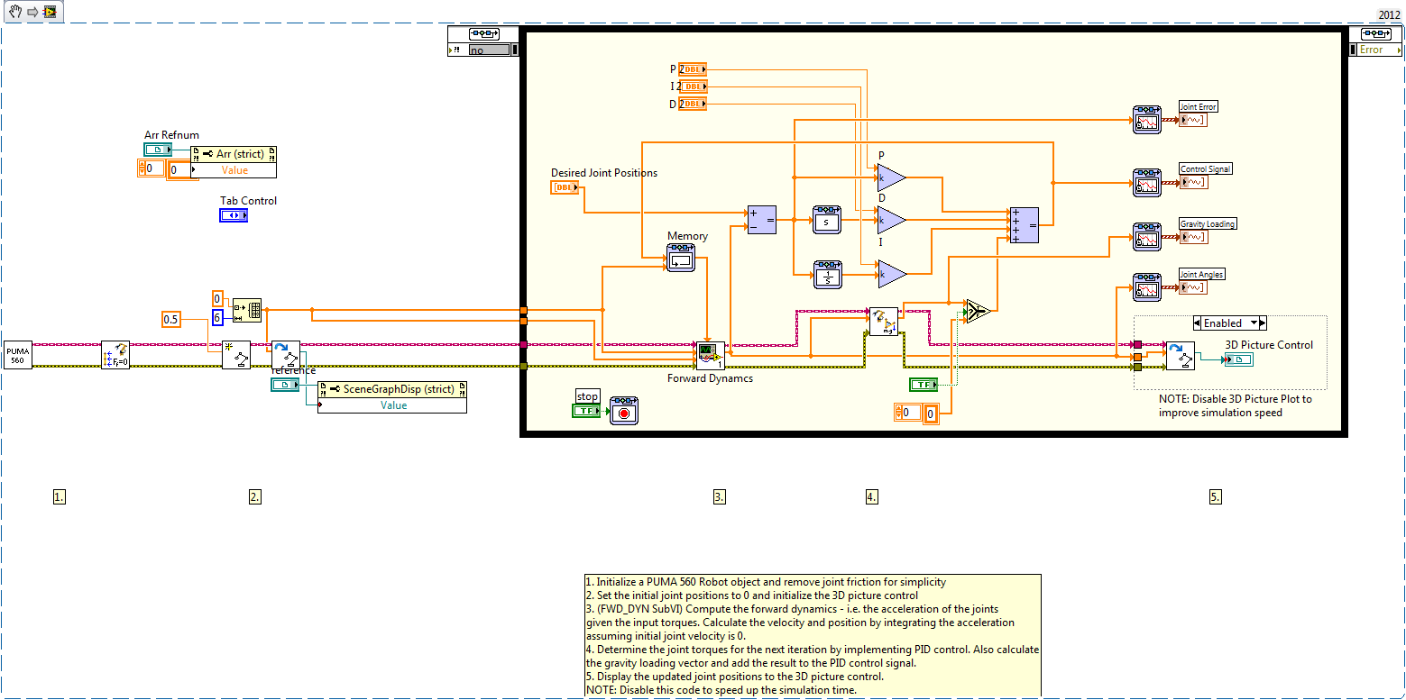
This example demonstrates how to use the LabVIEW Robotics Module and Control Design and Simulation Module 2011 to simulate the dynamics of a PUMA 560 Robot and a PID control scheme with gravity compensation used to achieve setpoint control. Gravity compensation accounts for the joint torques induced by the weight of the arm, which changes based on the joint positions.
Steps to Implement
- Download the attached files, "Puma_PID_GravComp_CD&Sim.vi" (top-level) and "FWD_DYN.vi" (SubVI) and place them in the same folder.
- Run the top-level VI.
- Change the "Desired Joint Position" inputs to non-zero values which represent the desired joint positions in radians. Tweak the PID gains and observe the changes to the response of the arm. Toggle Gravity Compensation On/Off to see the effects of gravity compensation.
Once the code is open:
Top-level VI
- Initialize the simulated Puma 560 robot arm
a) The "Create Puma 560" SubVI in the Robotics Module loads the DH Parameters of the Puma 560 as well as the dynamic paramaters such as joint mass, centre of gravity, friction parameters, etc.
b) Set the initial position of the robot arm joints to zero
c) Initialize the graphcs and draw the initial position of the arm
FWD_DYN SubVI:
2. Simulate the forward dynamics of the arm (calculate the acceleration given the torque input) using the Control and Simulation loop
a) Call the "Calculate Joint Acceleration" VI to determine the acceleration of each of the joints based on the current joint position and velocity vectors, as well as the input torque at each joint (which is determined by the PID control scheme)
b) Integrate the joint acceleration to obtain joint velocity, assuming that the initial joint velocity (at time zero) is zero
c) Integrate the newly obtained joint velocity to obtain joint positions, taking into account the initial position of the arm (at time zero) as the initial condition for integration
Top-level VI:
3. Determine the torque by implementing a PID control scheme on the position error and feed this torque to the forward dynamics block in the next timestep. Gravity compensation is achieved by calling the Gravity Loading VI in the Robotics toolkit.
Requirements
LabVIEW 2011 or higher with the Robotics Module and Control Design and Simulation Module

**This document has been updated to meet the current required format for the NI Code Exchange. For more details visit this discussion thread**
Example code from the Example Code Exchange in the NI Community is licensed with the MIT license.
