NI IQ SIM - Multi-Carrier Generation Tool
- Subscribe to RSS Feed
- Mark as New
- Mark as Read
- Bookmark
- Subscribe
- Printer Friendly Page
- Report to a Moderator
Code and Documents
Attachment
Specifications
- Combine 2 or more individual carrier signals of same or different radio access technology
- Dual-carrier scenario suffices for now
- Target radio access technologies: LTE, WCDMA, GSM
- Source signals (individual carriers) come from:
- Waveform files (e.g., TDMS)
- Output by RAT-specific toolkit or reference architecture
- Off-line/non-real time operation
- Intention is to run signal generation rarely simply to create a pool of test signals for a specific set of test task
- Input signals could be generated successively one-by-one
- Output signals can be saved on disk to be replayed during actual measurements
- Software should work with Piranha, Nyquist, (LTE) toolkits, RFmx
- Smooth integration when installed in parallel to any of these (no file/VI name conflicts etc.)
- Accepts as input formats those used in these software parts
- Provides output in formats used by these software parts
- "Atomic" software
- There should be no dependency on/call to any larger application or any specific (RAT) flavor of Piranha, Nyquist, RF toolkits, RFmx
- Signal generation should be possible without any dependency on HW, i.e., instrument calls
- Individual carriers characterized by:
- Bandwidth up to 20 MHz
- PAPR up to 13 dB
- Frame durations 10 ms (LTE, WCDMA) and ~4.6 ms (GSM)
- Multi-carrier signal characterized by:
- Bandwidth up to 200 MHz (E-UTRA operating bands 42 & 43)
- Signal durations 10...100 ms
- Baseband filtering of individual carriers:
- Avoid aliasing in resampling and combination process
- Trade-off low ACPR vs. low EVM (capability of R&S tool)
- Filter parameters:
- Type: square (LTE), RRC (WCDMA)
- Roll-off factor
- Cut-off frequency
- Resampling of individual carriers to target output sampling rate
- Output sampling rate adapted to larger bandwidth
- Frequency offsets: customer desires variable offsets, e.g.
- Adjacent placement of carriers
- One carrier each at the operating band edges
- Generated signal should be continuous, specified carriers should be rounded to avoid phase jumps when the waveform is repeated over and over again.
- Carrier powers
- MSR test spec (3GPP TS 37.141) calls for same power per carrier
- # of periods:
- Main use case is to create a periodic multi-carrier signal from individual carriers of different lengths, i.e., 6x LTE frame equals 13x GSM frame
- Optional, individual carriers could be generated with the appropriate length by the respective toolkit
- Time delay: needed, e.g., to generate WCDMA multi-carrier test signals from single-carrier TMs with (3GPP-) specified temporal offsets; simulates multi-carrier signal with realistic level of PAPR
- Initial phase: for full control of how the carriers are combined; may be important in tuning PAPR of multi-carrier signal
- PAPR optimization through phase variation: select phases of individual carriers to maximize or minimize PAPR of resulting multi-carrier signal
- Optional, automatic and iterative process
- Pick random phases
- Maximum number of trials
- Metric of convergence?
- Available with R&S signal generation software
Results
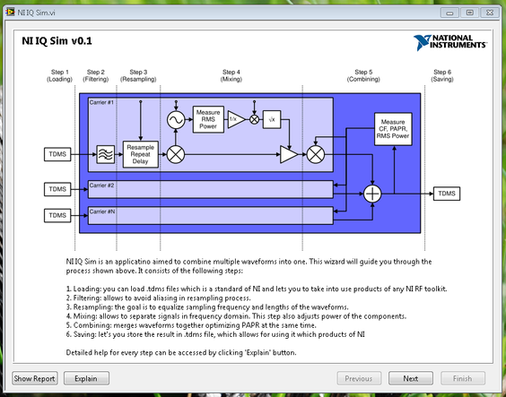
- As an input application uses TDMS files from any NI Toolkit
- As an output application provides a TDMS file, which can be processed even further
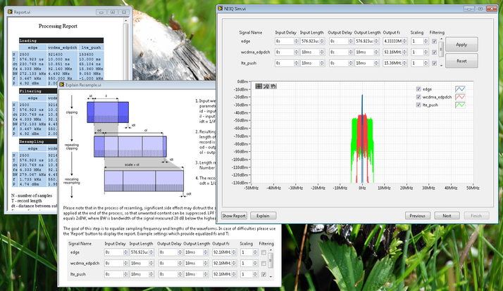
- Wizard-like user interface
- Examples of usage
Usage Notes
The application loads all the signals to the memory and processes everything in-place. This means that the length of signals are limited by the amount of RAM available for LabVIEW.
If you encounter this to limit you while processing multiple signals, you can process them in pairs (e.g. combine signal 1 and 2 to get 1+2, then combine 1+2 with 3 to get 1+2+3 etc.).
Known Issues
Measuring the EVM on a WCDMA signal after passing it thorough the software seems to give invalid results.
FAQ
What happens to the quality of the signal after combining?
Resulting quality directly depends of the processing which user applies. e.g. clipping and/or resampling can blur the signal in frequency domain because of spectrum leakage. Windowing could lower this effect, but it is not implemented at the moment. Particularly undersampling without proper filtering may result in aliasing. Level of these effects depends of the signal content and parameters of processing. So there is no simple answer to this question.
Application itself uses floating point representation, so numerical errors are negligible.
Please note that I and Q are resampled separately using spline interpolation. Alternatively we can consider resampling magnitude and phase if one considers this as more proper. It's not implemented though.
How is dynamic range impacted by combining diff signals?
Dynamic range remains the same as the definition describes it. So it's the difference between the highest component of the signal and the noise floor. As you combine multiple signals, the highest component counts here. Sum of the noise floors becomes a new noise floor. So again - it depends of the signal contents.
Please also note that the application in it's current version doesn't do any vertical scaling/shifting.
Which toolkits, if not all, will produce the appropriate TDMS file?
All the toolkits that I tried support TDMS. I don't have the list of them, but I believe these were: LTE. WCDMA, GSM, BT, WLAN.
Application always processes the first waveform in the file. It is assumed to be of a 'Waveform' type, where the samples are complex. IQ rate is determined based on NI_RF_IQRate attribute. A few of the toolkits may not provide such attribute. In these cases user must add it to the TDMS file manually.
Are there slides that were created for this tool?
I don't have any extra documentation/slides prepared for this application. Every page of the wizard has an "Explain" button though. I assumed it is sufficient for the user.
Created by Grzegorz Krason - Systems Engineer
Any attached Code is provided As Is. It has not been tested or validated as a product, for use in a deployed application or system, or for use in hazardous environments. You assume all risks for use of the Code and use of the Code is subject to the Sample Code License Terms which can be found at: http://ni.com/samplecodelicense
National Instruments
RF Systems Engineer
Example code from the Example Code Exchange in the NI Community is licensed with the MIT license.
- Mark as Read
- Mark as New
- Bookmark
- Permalink
- Report to a Moderator
Hi, your images are currently linking to internal NI resources that external will not be able to see.
National Instruments
Product Owner - ni.com Chat
- Mark as Read
- Mark as New
- Bookmark
- Permalink
- Report to a Moderator
Hello,
Sorry for the late response. I have fixed it.
Regards,
Kornél Nagy
National Instruments
RF Systems Engineer


