Multi-Function TEC (Peltire) Controller
- Subscribe to RSS Feed
- Mark as New
- Mark as Read
- Bookmark
- Subscribe
- Printer Friendly Page
- Report to a Moderator
Overview
This VI was originally designed for testing and controlling various types of thermoelectric coolers (TEC / Peltier) by using a programmable power supply, CompactDAQ + C modules as well as a PID Control algorithm. While this application was specifically developed for TEC, it may also be used for other slow speed applications requiring a PID controller. Additional features include Auto/Manual mode, delta temperature set/monitor warning, real-time process variable versus target temperature strip chart, parameter monitoring and data logging.
The PID section uses three analog input channels for temperature sensor inputs (hot/cold and ambient), a digital line to generate a low frequency (few hertz) pulse width modulated (PWM) output to power the TEC under test. When the advanced PID algorithm is in manual mode, you can set the output power level (pulse width) anywhere from 0 to 100% by adjusting the “%Manual Power Control” knob. When in auto mode, the pulse width is adjusted according to the PID gain setting.
The power supply section consist of programmable voltage ranging from 0 to 50 volts at 7Amps (model dependent), up to 21Amps with multiple power supplies connected in parallel, power output polarity control, fan control in continuous or PWM mode, emergency shutdown as well as waveform strip chart in addition to the parameter monitoring displays.
How It Works:
The ambient temperature is used for reference, temperatures above ambient are considered “Hot” and temperatures below ambient are “Cold”. For hot temperature controlling, TC0 is used as a feedback to the PID controller, and for the cold temperature TC1 is used for feedback. Figure 1 is simplified block diagram of the multi-function TEC controller.
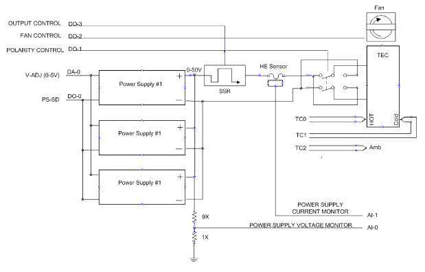
Figure 1. Multi-Function TEC Controller Block Diagram
Power Supply Main Features:
- Programmable power supply from 0 to 50 volts with 100mV resolution
- Power supplies can be paralleled for higher output current and controlled via only one DAC (digital to analog) and one digital line for power shut-down
- Power supply polarity control for reversing the output voltage therefore changing from hot to cold
- Fan control switch for continuous or Pulse Width Modulation (PWM) operation
- Parameter monitoring (voltage, current and power) plus strip chart for real-time view of the applied power
- Emergency shutdown
PID Controller Main Features:
- Target temperature from -20 to 120°C
- Delta temperature from 0 to 120°C
- Auto/Manual control
- Target versus processed temperature chart
- Parameter display, T-Amb, T-Hot Side, T-Cold Side, T-Delta
- Data Logger
Instructions: Power supply setting:
- 1. Set the voltage to appropriate value for TEC under test (default is 12 volt)
- 2. Set the Pol Ctrl (Polarity Control) switch to positive or negative (default is positive)
- 3. Set the “Fan-Ctrl” switch to Continuous (up) or “PWM” low (default is continuous)
- 4. Turn on the power and monitor the voltage
Instructions: PID Controller:
- 1. Set the desire temperature (default is 50°C)
- 2. Set the desire delta temperature (default is 50°C)
- 3. Adjust the PID gains (default is 10,01 and 0)
- 4. Start the PID
Hardware:
- NI cDAQ-9174 (CompactDAQ)
- NI 9211: 4-Channel Thermocouple Input Module
- NI 9201: 8-Channel, 12-Bit Analog Input Module
- NI 9263: 4-Channel, 16-Bit Analog Voltage Output Module
- NI 9475: 8-Channel, 60V, Sourcing Digital Output
Thermocouple inputs:
Three thermocouple input lines are used for monitoring temperatures as follows:
- TC0: TEC hot side temperature
- TC1: TEC cold side temperature
- TC2: Ambient temperature
Analog inputs lines:
Two analog input lines are used for monitoring power supply voltage and current as follows:
- AI-0: monitors power supply output voltage (with 1/10 voltage divider)
- AI-1: monitors output current (100mV/A – 2.5V ref voltage)
Analog output:
One Analog output line is used for adjusting power supply output voltage (0 to 5V corresponds to 0 to 50V)
Digital I/O Lines:
Four digital lines are used for controlling power supply, relays and fan as follows:
- DO-0: power supply shutdown
- DO-1: Output power polarity control relay
- DO-2: Fan Control
- DO-3: Output power control (e.g., PWM) with a solid state relay (SSR)
The following 3 figures are sample snapshots of TEC at various operating condition.
 Figure 2, TEC default setting
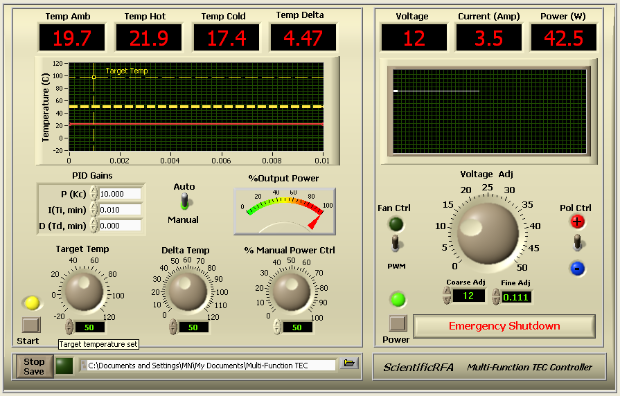
Figure 3, TEC with DC voltage supply
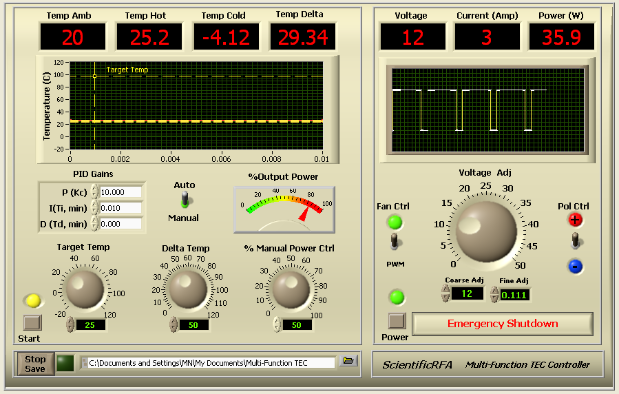 Figure 4, TEC with PWM output control
The following videos demonstrate different scenarios using the Multi-Function TEC controller system.
PID temperature controller from sub-zero to near boiling water demo
CPU Cooler Performance Test
Extreme Sub-zero Temperature Regulator
Example code from the Example Code Exchange in the NI Community is licensed with the MIT license.
- Mark as Read
- Mark as New
- Bookmark
- Permalink
- Report to a Moderator
It requires a "SimX.xnod" to run this vi. But what's that?
THX~
- Mark as Read
- Mark as New
- Bookmark
- Permalink
- Report to a Moderator
Where can I get the code of this Labview program
