From Friday, April 19th (11:00 PM CDT) through Saturday, April 20th (2:00 PM CDT), 2024, ni.com will undergo system upgrades that may result in temporary service interruption.
We appreciate your patience as we improve our online experience.
From Friday, April 19th (11:00 PM CDT) through Saturday, April 20th (2:00 PM CDT), 2024, ni.com will undergo system upgrades that may result in temporary service interruption.
We appreciate your patience as we improve our online experience.
In my previous post (https://decibel.ni.com/content/docs/DOC-48590), I released a library which allows a Labview user on Windows to directly use RTL-based software defined radios. The implementation process was very straightforward because the library was already compiled and available in binary form. Additionally, because the library is open source, header files and with that the library’s entry points are available to us in a usable and documented format. In this post I will go a step further and show the reader how to compile the rtlsdr library directly on an RTLinux cRIO. I used a myRio to do this project, but it should be possible to use this information on any linux-based cRio. Unfortunately, there is probably no reasonable way to compile this library on VxWorks, much less Pharlap, so users of older CompactRIO devices are on their own.
NOTE: All development was done using Labview 2016, 32-bit. The myRIO used here has the following parameters:
Operating System | NI Linux Real-Time ARMv7-A 4.1.15-rt17-ni-4.0.0f1 |
Firmware Version |
|
Real-Time Software Version | Labview Real-Time 16.0.0 NI myRIO 16.0 - August 2016 |
If we want to use the cRIO (especially the FPGA) to accelerate digital signal processing, it is necessary to stream the information to the RT system, and then to the FPGA.
|
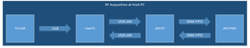
Host Acquisition Architecture |
If the host is used for acquisition, the information flow is pictured above. The information flows from the RTL-SDR to the Host PC via USB, then to the RT system via USB LAN (in the myRIO case), then to the cRio FPGA via a DMA FIFO. The FFT and other DSP is done in the FPGA and the resulting information flows back up to the PC.
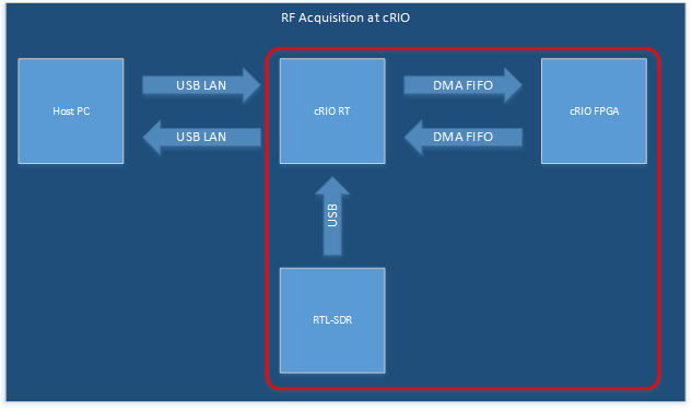
In order to shorten this path it is possible to perform the acquisition directly on the cRio RT target. This has the advantage of getting rid of the latency of the USB LAN connection during acquisition. However, it also makes things more complicated because a command framework is required from the Host PC to the cRIO RT target. Simply put, we want to turn the myRIO into an SDR-instrument that we can send commands to and have it return processed data to the host.
In order to keep the reader interested and to keep the chapters short and manageable, I have decided to split things up a bit. This leads the reader chapter by chapter to a full solution, and hopefully makes things more understandable. In this tutorial, we will be focusing on getting the rtl-sdr library working on in the cRIO. The next tutorial will implement and FPGA FFT to accelerate things, and in chapter 4 we will put this whole thing together into a coherent, expandable system.
This tutorial therefore focuses on this portion:
|
RT Acquisition |
Before beginning with actual Labview programming, we need to prepare the cRIO. This includes setting up the build environment on the cRIO, cloning the git repository for the rtl-sdr library, and finally compiling the code. This may sound hard, but it really isn't. This tutorial will guide you through the process.
NOTE: All steps assume the cRIO has internet access. Without internet access, this will not work. If using the myRIO, the easiest way to do this is to configure the Wi-Fi interface to that it connects to your internet hotspot and acquires address, dns, gateway via dhcp.
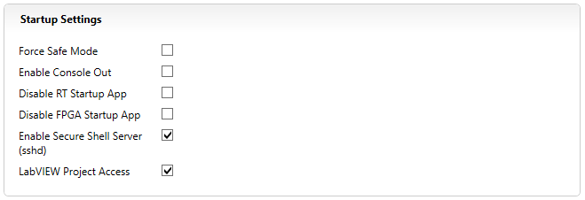
Open MAX, then open your RIO. Under startup settings there will be an item called "Enable Secure Shell Server (sshd)". Make sure the checkmark is set. This will allow you to access the Linux command line remotely via ssh. Before you get worried and stop reading, let me just mention that I have documented all commands and you can simply cut and paste them into the console. Even if you are a Linux “n00b”, you shouldn’t have problems getting this to work. However, if problems do arise, please feel free to ask.
|
Enabling SSHd |
Continuing on, please verify the system time in the "Time Settings" tab. If the time is not set properly, you will get warnings during compilation. I'm not sure if they are detrimental to the process, but they are ugly nonetheless and can easily be prevented by setting the time properly.
When you save the changes, MAX will ask for a reboot. Confirm and let the cRIO reboot.
Now that sshd is up and running, we can use an ssh program such as putty to connect to the CompactRIO and get console access. Putty is available on the internet for free and my personal favorite. The username of the cRIO is admin, and the password is blank unless you have changed it in MAX.
Now that we are at the console, please verify that we are in the /home/admin directory. This should be the default directory upon connection. You can verify this by typing in pwd and pressing enter. Pwd stands for "print working directory" and prints the current directory to the console.
If we want to compile code on a cRIO, it's necessary to install a c compiler and some support packages. These are not installed per default because technically a cRIO is not a system to build on. Rather it's a target to run binaries on. However, National Instruments was kind enough to create a repository with many, many Linux packages in it. We will be installing from this repository.
Please run the following command:
opkg update && opkg install libusb-1.0-dev gcc gcc-symlinks git cmake binutils autoconf automake libtool boost-dev pkgconfig make
This will update the local package cache and install the required compilers and support tools. You can copy and paste this command directly into the console.
Should this command fail, you may not have internet access on your cRio device.
The next step is to create a local copy of the rtl-sdr library’s code on the cRio. The source code for the rtl-sdr library is stored in a code repository at osmocom which uses git. If you are unfamiliar with git, you may be familiar with cvs, svn, or scc. It’s a source code control and versioning system. If you are unfamiliar with source code versioning and source code control, it’s about high time you got up to speed. Version control is a key component of professional software development. Creating a local copy of this repository is called cloning.
To clone the repository, please execute the following command (again, you can copy and paste this directly into your ssh session):
git clone git://git.osmocom.org/rtl-sdr.git
This will copy the entire source code to a subdirectory called rtl-sdr.
To compile and install the library, simply execute the following commands:
cd rtl-sdr/
mkdir build
cd build
cmake ../
make
make install
ldconfig
cmake ../ -DINSTALL_UDEV_RULES=ON
This will compile the library and install it in /usr/local/lib/librtlsdr.so. Additionally, some binaries will be installed, such as rtl_test and rtl_fm. You may check the details on what the binaries to on osmocom's rtl-sdr website: http://sdr.osmocom.org/trac/wiki/rtl-sdr#Buildingthesoftware.
If you have an rtl-sdr supported device, you can plug it in now and verify that it's working by typing in rtl_test. If you see output along the following lines, you're set to go.
Found 1 device(s):
0: Realtek, RTL2838UHIDIR, SN: 00000001
Using device 0: Generic RTL2832U OEM
Found Rafael Micro R820T tuner
Supported gain values (29): 0.0 0.9 1.4 2.7 3.7 7.7 8.7 12.5 14.4 15.7 16.6 19.7 20.7 22.9 25.4 28.0 29.7 32.8 33.8 36.4 37.2 38.6 40.2 42.1 43.4 43.9 44.5 48.0 49.6
[R82XX] PLL not locked!
Sampling at 2048000 S/s.
Info: This tool will continuously read from the device, and report if
samples get lost. If you observe no further output, everything is fine.
Reading samples in async mode...
lost at least 116 bytes
rtl_test is a good tool for verification and testing of the functionality of your rtl-based software defined radio. In addition to verifying that the library is installed properly and that your system recognizes an rtlsdr when plugged in, it also allows the user to obtain the frequency correction. Each and every dongle has a unique frequency correction value which should be determined and then passed to the library. To do this simply run
rtl_test -p
at the command line. This will cause the application to output the ppm value every 10 seconds. The first ppm value is the last measured frequency correction, the second is the cumulative frequency correction. You will notice that this value varies widely at first. This happens because the chip warms up and as we all know oscillators have a thermal drift. Leave that running for a couple of minutes. When the cumulative ppm doesn’t change anymore, record that value. You will notice that the ppm value varies wildly at first. This is because it takes time for the dongle to warm up. After a few minutes the output should look like this:
real sample rate: 2048144 current PPM: 71 cumulative PPM: 54
real sample rate: 2048088 current PPM: 43 cumulative PPM: 53
real sample rate: 2048122 current PPM: 60 cumulative PPM: 53
real sample rate: 2048096 current PPM: 47 cumulative PPM: 53
real sample rate: 2048107 current PPM: 53 cumulative PPM: 53
real sample rate: 2048118 current PPM: 58 cumulative PPM: 53
This means that this particular rtl-sdr has a frequency correction value of 53 ppm. The library provides a function to set this value. However, as mentioned before, these are very simple devices (what were you expecting for $20.00 or so) so you will never be as accurate as professional level SDR.
That's it, you're done on the console. You are now ready to use the library in Labview Real-time.
Important: If security is an issue (and it should be), disable sshd by removing the checkmark in MAX. You can always re-enable this if you need access to the console again.
Now that we have compiled the library, we can use it from any vi running on the rt target. I have rewritten all the vi’s in the library released in chapter 1 and am making them available as part of the attached project. Basically, the only difference is the location where the library resides. That is all that is necessary to use the device.
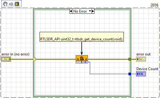
Running on Labview for Windows | |
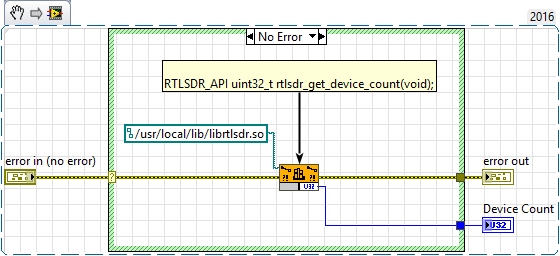
Running on Labview RT | |
As you can see, the only difference between the two is that we specify the library path directly on the block diagram. If you open the “call library function” node, you cannot browse to the library on the target system. It will just open the development computers file system. This happens because during edit time, the system has no access to the targets file system. Not sure if there is a way around this.
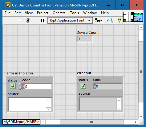
The easiest way to verify that the library is working is to execute the function “Get Device Count” directly on the RT Target. You can run this vi standalone as it does not require an open handle to the device. It simple runs a function inside librtlsdr.so to check how many rtl-sdr devices are present in the system. If run this, and the vi shows a 1 in the device count indicator, the system works as it should.
|
Get Device Count Output running on the RT Target |
As in my previous post, I’ve included a small example to show how the functions are to be used. Note that you may have to adapt the RIO settings to match your target. Note that as this is just an example and is for explanation only, the style guidelines have not been exactly followed. Especially with the size of the vi. It was written linearly from left to right so the reader can easily follow the flow without having to work through a complex state machine or queued message handler. Also, there is little to no error handling implemented. It is for demonstration purposes only.
Open the RT_Main.vi under mySDR/RT/.
|
Project Structure |
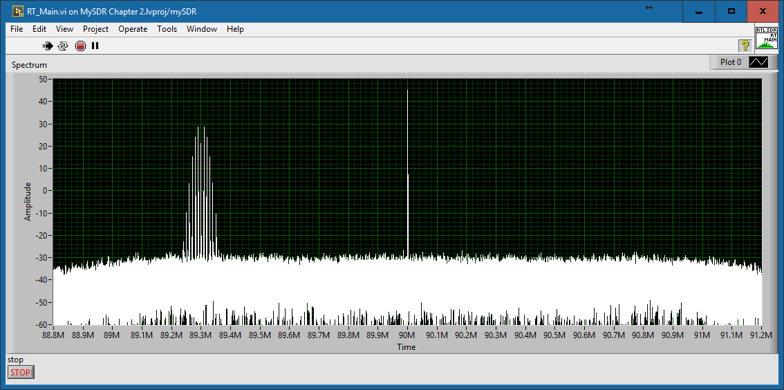
Using a calibrated, high quality signal generator, I have generated a two tone fm signal at 89.3 MHz. As you can see from the following screenshot, the running on the rt target, acquisition and processing run perfectly well on a myRIO. Again, please note the DC spur at the center frequency. Refer to my previous post for an explanation and further sources for information on this.
|
Spectrum Display |
Now that we can acquire, process, and display from an rtl-sdr directly on an RTLinux based cRIO, we can begin the next step, and that is to offload signal processing of the RTLinux target onto the FPGA. Then our architecture will look like this:
|
Architecture Chapter 3 |
So stay tuned...
I really hope this will be useful to someone. As with anything, your mileage may vary, but feel free to ask questions if you have problems getting something to work. If it's withing my power, I will be more than glad to help.
Example code from the Example Code Exchange in the NI Community is licensed with the MIT license.
Very informative article. Using this scheme, we can connect alot of other devices to LabVIEW-RT.
Thanks for sharing this.
Добрый день!
Подскажите, пожалуйста, как получить разность фаз от 3-х SDR-приемников на заданной частоте сигнала?