From 04:00 PM CDT – 08:00 PM CDT (09:00 PM UTC – 01:00 AM UTC) Tuesday, April 16, ni.com will undergo system upgrades that may result in temporary service interruption.
We appreciate your patience as we improve our online experience.
From 04:00 PM CDT – 08:00 PM CDT (09:00 PM UTC – 01:00 AM UTC) Tuesday, April 16, ni.com will undergo system upgrades that may result in temporary service interruption.
We appreciate your patience as we improve our online experience.
To download NI software, including the products shown below, visit ni.com/downloads.
Overview
Some applications require very tight synchronization between two or more generation modules within the same chassis. For some specific applications such as envelope tracking, a very precise but non-zero delay is required between two generating devices (for example, to align the output waveforms after going through unequal signal paths). The NI-TClk technology is very useful for aligning sample clocks and synchronizing devices, and its SampleClockDelay property is useful to generate such delays. However, it is restricted to +-1 period of the sample clock. This example demonstrates how to achieve any delay between two devices with high precision.
Description
This example configures two FGEN devices (compatible with TClk and Script Output Mode). By configuring a desired Sample Rate and Delay, the user can easily define the level of synchronization between the two devices. The delay can be defined by two settings - "coarse" delay consisting of a Wait statement in a device script (2n samples, or 2n periods), and a "fine" delay that adjusts the Sample Clock Delay TClk property (up to +-1 period). Together, the coarse and fine delays allow any level of synchronization.
Note that this delay accuracy is most relevant in sample rates above 100MS/s, where subnanosecond resolution is desired.
Requirements
Software
LabVIEW 2012 or later
NI-FGEN 2.9.1 or later (includes NI-TClk 1.9.2 or later)
Hardware
PXI or PXIe chassis
2 high speed FGEN devices compatible with TClk and Script output mode (such as the PXIe-5450)
(optional) High Speed scope with 2 channels (for example, a PXI-5152)
Steps to Implement Code
Additional Information or References
Block Diagram:
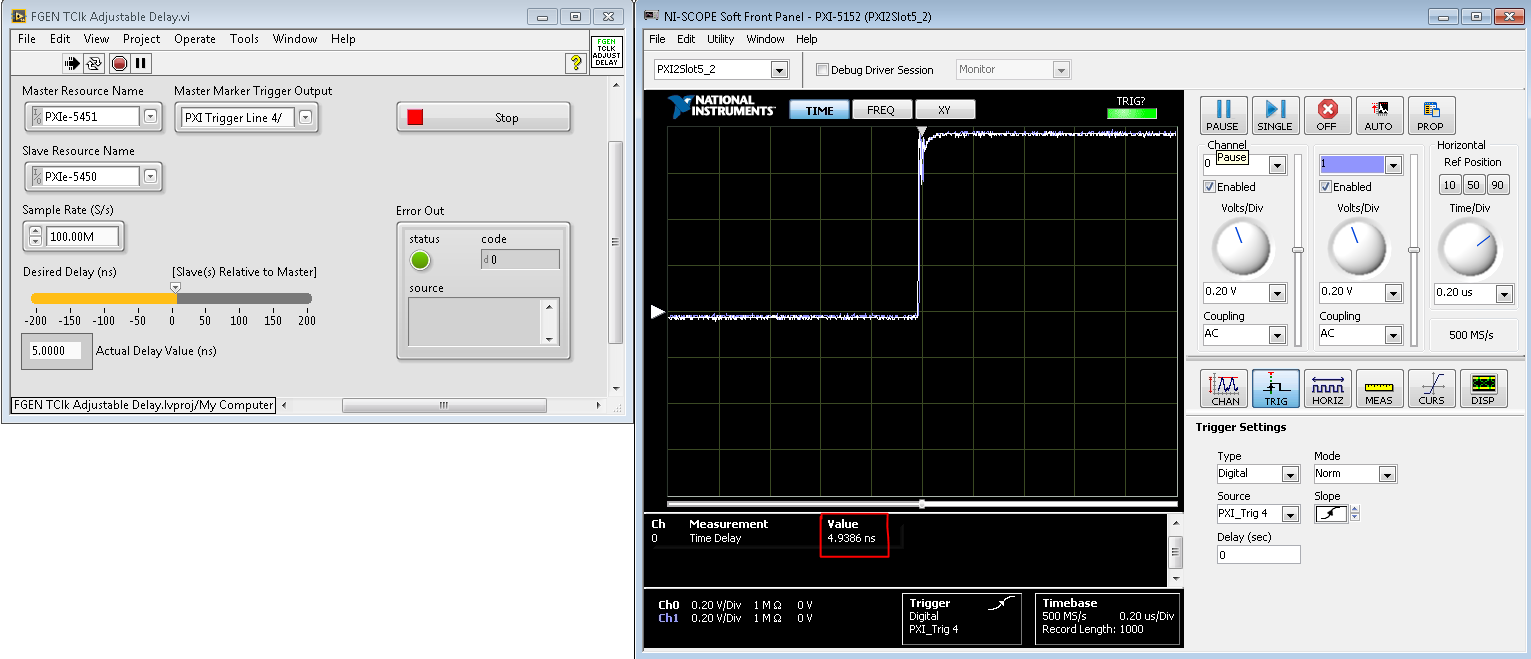
The following screenshots are taken to illustrate the synchronization capabilities.
Hardware used:
PXIe-5450 and PXIe-5451 in a PXIe-1078 chassis
PXI-5152 (8-bit, 2GS/s Digitizer)
PXIe-5451 connected to Ch0, PXIe-5450 connected to Ch1
Set to Trigger on a Digital Edge on PXI Trigger Line 4
Horizontal Resolution of 0.20 us
Time Delay Measurement between Ch0 and Ch1
Sample Rate = 100 MS/s, Desired Delay = 5 ns:
Sample Rate = 100 MS/s, Desired Delay = 50 ns:
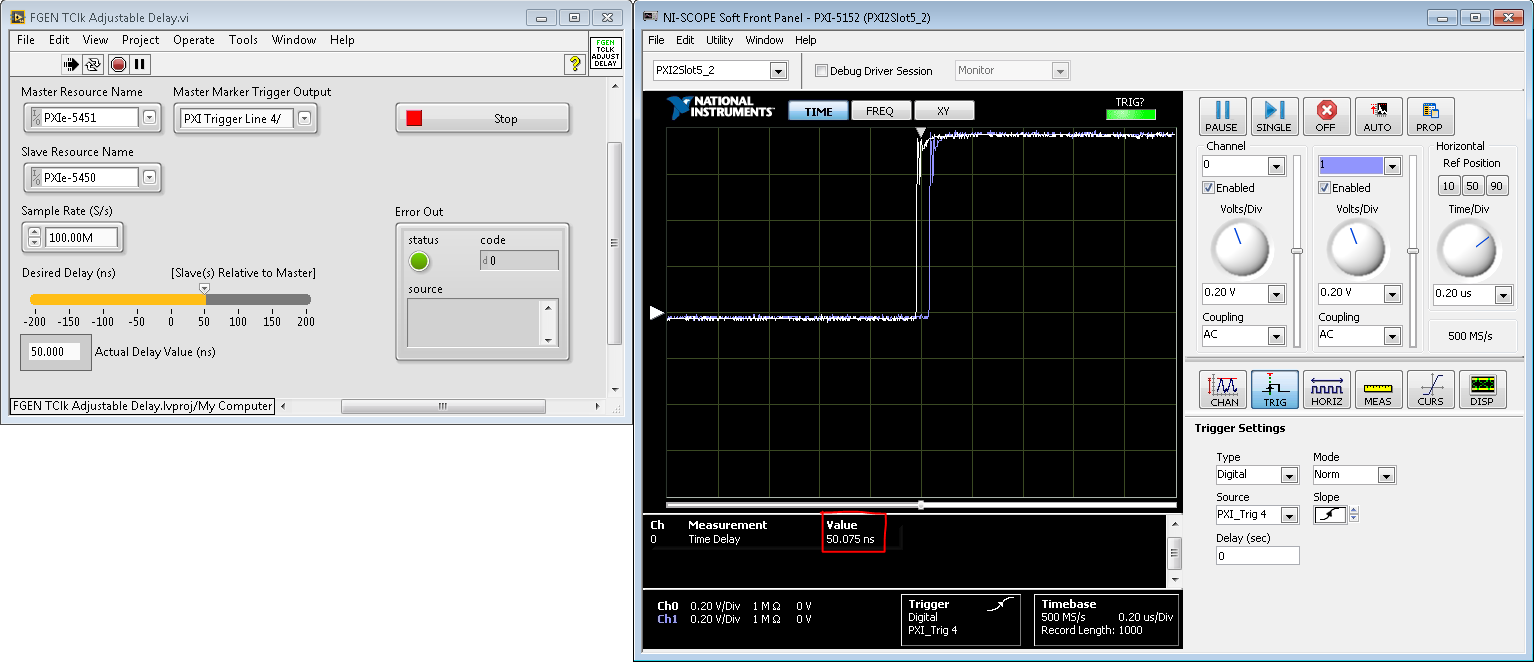
Sample Rate = 100 MS/s, Desired Delay = 150 ns:

**This document has been updated to meet the current required format for the NI Code Exchange.**
Example code from the Example Code Exchange in the NI Community is licensed with the MIT license.
Great example using the Channel Delay Property.

