From Friday, April 19th (11:00 PM CDT) through Saturday, April 20th (2:00 PM CDT), 2024, ni.com will undergo system upgrades that may result in temporary service interruption.
We appreciate your patience as we improve our online experience.
From Friday, April 19th (11:00 PM CDT) through Saturday, April 20th (2:00 PM CDT), 2024, ni.com will undergo system upgrades that may result in temporary service interruption.
We appreciate your patience as we improve our online experience.
For developing instrument drivers, please follow documentation available at the following locations:
In order to ensure drivers are compatible with LabVIEW Real-Time, which means they are safe to use in deterministic applications, there are extra precautions to take when developing deterministic drivers for LabVIEW Real-Time. The following documents will aid in getting started with developing instrument drivers for Real-Time:
Please contact NI Partner Program engineers for more information regarding compatibility testing for instrument drivers to be used in LabVIEW Real-Time.
For a broad set of development guidelines please consult the following LabVIEW Help documents:
A VI-based API is a library of VIs which support the building of applications by providing a user with high-level functions to perform complex tasks. For example, the National Instruments DAQmx driver can be used to acquire data on the analog input channel of a data acquisition board and the user does not need low-level understanding of how to communicate with hardware in order to perform this task. The data acquired through use of the DAQmx driver API can then be used to create a Microsoft Excel report with another API, the LabVIEW Report Generation Toolkit for Microsoft Office, which makes ActiveX function calls without the user needing to understand or learn ActiveX. Both of the VI-vased APIs in this example provide the user with high-level VIs to perform sometimes complex operations without the need to understand low-level functionality.
It is important to adhere to a set of design guidelines and be consistent when developing API VIs; doing so ensures consistency within the API itself and with other similar APIs. Most APIs follow a common design pattern with three groups of functions:
Initialization/configuration VIs
VIs to perform operations
VIs for clean-up
This document will aid in establishing requirements for your set of design guidelines.
When designing an API, provide users with the ability to develop both simple and advanced applications. This can be accomplished by making common functions obvious to users, while also allowing for more advanced applications by including more complex functions as well. Simple tasks should require a few VIs and not include obscure controls, while less common use cases could require more VIs and more obscure controls. It is important to document both simple and complex functions and it is acceptable to require users to consult documentation for information about using more advanced functions.
One important concept for developing an API is to understand the API VIs will be used as subVIs in user applications. An API with a few high-level VIs may not provide the user with enough control over a desired operation; while in contrast, an API with many low-level VIs might be too complicated for users who are unfamiliar with the rules regarding command order and interaction for the API. Understanding the application needs of the customer can help you define the correct level of granularity for developing VIs as subVIs.
It is acceptable to include low-level VIs to provide users with more control over operations, or to provide users with the ability to execute more advanced functionality. However, if included, they should not cause confusion to the majority of users. Place low-level VIs several layers down in the VI hierarchy. Generally, the approach to developing higher level VIs is to incorporate several similar low-level VIs.
It is also important to design an API so all VIs work well together within the API. To accomplish this, design the data types and terminal patterns of each VI to work well with each other. For example, many National Instruments APIs use a consistent 'reference' parameter throughout the API VIs. Ensure the consistent parameter for an API appears on the connector pane in the same terminal position on each VI. The following block diagram illustrates an API where VIs use a common reference parameter (blue/green wire) and error parameter (yellow wire).
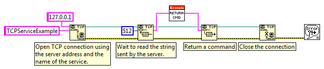
Figure: Example of consistent wiring within the API VIs.
The following block diagram illustrates subVIs designed with inconsistent terminal patterns, which leads to inconsistent controls and wiring.
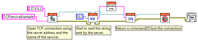
Figure: Example of bad terminal selections with inconsistent terminal locations. Notice the error wires and reference wires are not straight due to inconsistent connector pane patterns.
In order to help users control data flow and to force data dependency in their applications, use the error in and error out parameters, along with other parameters consistent or common among your VIs. For example, both of the figures above use error parameters (yellow wire) and a common reference wire (blue/green) to control data flow and force data dependency. Data flow determines the order in which LabVIEW programs execute. Design APIs so users can take advantage of this paradigm. By using error in, error out, and other parameters consistent in each of the driver API VIs, you add data dependency to VIs that otherwise are not data dependent. This gives users a way to specify execution without using 'Sequence' structures. After the error cluster passes data through all of the API VIs, the end-user application can use the General Error Handler VI or Simple Error Handler VI (which interprets error codes and displays messages to the operator) to handle errors.
When creating the file structure for a VI-based API, be sure to use folders to organize files on disk. Using LLBs for file storage is no longer preferable. Storing VIs in folders ensures seamless integration with source code control software, which is crucial for success in multi-developer environments. It is recommended development practice to use a Source Code Control utility for managing revision history as discussed in the Managing LabVIEW VI and Application Revision History document.
In addition to using source code control, it is important to keep your deployment requirements in mind when creating the file structure to store your source code. LabVIEW APIs are to be distributed to a folder within LabVIEW\vi.lib\Company Name\Product Name\. It is a best practice to create a folder for your product based upon this naming convention to prevent interference with other products. This naming convention or prefix will be used when naming folders and files elsewhere in this document in order to maintain some level of order and to prevent interference with other products. For a table containing recommended file and folder names please refer to the File and Folder Names for Integrating into LabVIEW document. Since most developers of APIs will develop their VIs outside of the National Instruments or LabVIEW directories, it is recommended to re-create the deployment folder structure in your development folder during development. For example, if you were to use c:\dev\ as your development folder for storing source code, the following folder hierarchy is recommended:
If you develop your API with the above hierarchy, where the deployment folder structure is replicated in your development folder, you will find the deployment process for your API is simplified. The set of code above could be included in a Source Distribution with the option selected to 'Preserve Disk Hierarchy', and an installer build specification could then be created in the Application Builder to distribute your files to the correct location in the LabVIEW directory. The Building an Installer for an API example discusses the deployment process in more detail.
In order to prevent the add-on folder hierarchy from becoming excessively nested, create a separate folder for each group of VIs in the API. The following image shows the folder hierarchy for the Sound and Vibration API (LabVIEW 2009\vi.lib\addons\Sound and Vibration), notice the use of folders to group files into sub-directories.
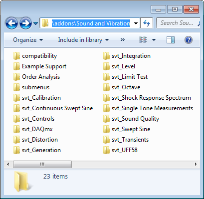
Figure: Example of grouping files into folders based upon groups of VIs in the API.
Many VI-based APIs use prefixes on the names of their VIs to avoid name collisions with other VIs in memory. The recommended approach is to use project libraries to establish a unique name space for a group of VIs. When VIs are members of a project library, they are name spaced by that library and thus do not need prefixes as long as there is not another project library in memory with the same name.
Another benefit of using project libraries is the ability to scope VIs in a library as being public or private. Public VIs compose an API, these are the functions users will access. Private VIs provide the “inner workings” of an API, users do not have access to private VIs and therefore the interface or functionality of private VIs can be modified without breaking existing user’s applications.
For more information on using project libraries, please view the ‘Using Project Libraries’ topic in the LabVIEW Help.
When developing the front panel for an API VI, it is not always necessary to create a complicated user interface when most API VIs are going to be called as subVIs. Some rules to follow are to consistently place controls and indicators common among the API VIs in the same location on the front panel; this helps to give the same look and feel to VIs within an API. A general rule followed by most APIs is to place front panel items with some relation to their location on the connector pane, controls on the left and indicators on the right with an order similar to the order in the connector pane.
When setting default values for VIs, try to choose a default value so the VI does not return an error when run. Be sure to avoid setting the default values for indicators as doing so uses unnecessary disk space when saving the VI.
Since fonts vary by platform, user system preferences, and video driver settings, text may appear larger or smaller on different systems. To allow extra space for larger fonts on control and indicator labels, ensure the option for 'Size to Text' is selected in the shortcut menu for the label.
A general practice to follow for developing front panels is to keep the front panel simple. Do not overlap controls onto other controls, labels, digital displays, or other objects as overlapped controls redraw slowly and tend to make the front panel appear cluttered. The 'alignment' and 'distribute objects' pull-down menus provide great tools for creating a uniform layout on a front panel. Also, to prevent confusion among end-users, try not to hide controls and indicators on the front panel as this can make debugging VIs difficult.
For the block diagrams of your API VIs, use a consistent style with labels on the block diagram to improve the readability of your code. Treat free labels as you would comments in text-based programming, proper use of free labels to document the code on the block diagram serves to aid not only end users who are trying to understand the application, but they also serve to aid in future development of the API. The image below demonstrates how to use free labels to describe the process of execution for a set of code:
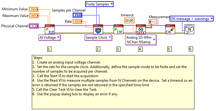
Figure: Example of how free labels can be used to document code.
Most VI-based APIs use similar data structures in their VIs. For example, there may be a cluster of configuration information used by several VIs in the same API. For cases such as this, it is always best to make type definitions of common control types; this ensures consistency between the VIs in an API and also eases code management when something about a common control must change. As a recommended development practice, clusters, enums, and any other complex data types used in more than one place in an API should be made into type definitions.
VIs in an API are to be used together and therefore should have consistent connector panes to facilitate clean wiring on a block diagram. It is also important to choose a connector pane pattern with enough empty spaces to allow for expansion of an API (new inputs/outputs). The 4x2x2x4 connector pane pattern is sufficiently large for most APIs, but sometimes the 5x3x3x5 pattern is necessary; it is important to choose a pattern and continue using the same pattern for the entire API.
Always place ‘error in’ and ‘error out’ terminals (for the yellow wires) in the lower left and right corners of the VI connector pane. If an API is reference-based, place the ‘reference in’ and ‘reference out’ terminals (the purple wires) in the upper left and right corners of the VI connector pane.
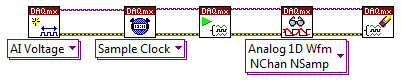
Figure: Example of good connector pane positions for error and reference terminals.
VI Icons for API VIs need to provide a visual indicator for each particular VI function, and all icons for a particular VI must follow a common theme or style. The LabVIEW 2009 Icon Editor provides a library of glyphs and frameworks to aid in icon development. The following document provides guidelines for creating professional looking icons:
When developing LabVIEW APIs for target-specific applications, it is important to follow the programming guidelines for a given target or module. For example, the LabVIEW RT and FPGA modules have target-specific programming palettes and requirements, and it is important to consult the help topics for each of these modules. Customer Education courses are also available through the NI Customer Education program for more in-depth training on programming practices to follow when developing software with these LabVIEW Modules.
For the Compact RIO Developer Guide please follow this link: http://www.ni.com/compactriodevguide/
When developing an API for LabVIEW, keep in mind some users will want to use the toolkit on other operating systems where certain functions are not supported. It is important to make a design decision for target operating systems and document this decision as a system requirement for the API.
For VI-based APIs, palettes must be created in order for users to effectively utilize the functions of the API.
Please refer to 'Creating a LabVIEW Palette' for an example on creating LabVIEW Palettes.
Use the palette editor (Tools > Advanced > Edit Palette Set) to interactively create .mnu files to represent the palette organization. For more information on how to create and edit palettes, click the Help button in the Edit Controls and Functions Palette Set dialog box to view the Help document.
Do not edit or replace any of the existing .mnu palette files when integrating into the palette set.
The recommended place to store palette menu (.mnu) files is in LabVIEW\menus\Categories (instr.lib or vi.lib\addons\ is also acceptable), which loads subfolders and .mnu files in respective categories in the LabVIEW palette set. We recommend the following approach:
Integrate your palette into one of the existing categories by either creating a folder for 'CompanyPrefix Product name' in one of the existing category folders, or by adding your .mnu file to one of the existing category folders (LabVIEW\menus\Categories). Be sure to use the 'CompanyPrefix Product Name' naming convention for the file or folder name, or name the folder 'Company Name' with subpalettes containing your separate products. Do not edit or replace any existing .mnu files.
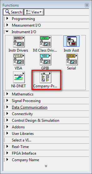
When integrating into the existing LabVIEW palette categories, the following table lists the palette category, the corresponding folder on disk, and whether or not it is locked from adding your palette to it:
| Palette | Folder Name (in \menus\Categories unless a path is provided) |
Locked? |
|---|---|---|
| Programming | Programming | Open |
| Measurement I/O | Measurement | Open |
| Instrument I/O | Instrument | Open |
| Instrument I/O > Instr Drivers | LabVIEW\instr.lib\ | |
| Vision and Motion | VisionMotion | Open |
| Mathematics | Mathematics | Open |
| Signal Processing | Signal Processing | Open |
| Data Communication | Data Communication | Open |
| Connectivity | Computer | Open |
| Control Design & Simulation | Design & Simulation | Open |
| SignalExpress | SignalExpress | Locked |
| Express | Express | Open |
| Addons | LabVIEW\vi.lib\addons\ | Open |
When developing target-specific APIs, it is important to document VIs only intended for use in a target-specific palette as users may mistakenly attempt to use the VIs in the wrong execution environment. The result of doing so is most often a broken run arrow if the target-specific API function includes dependencies from target-specific palettes.
In order to make an API available in a target-specific palette, the .mnu files and support files must be deployed to the target-specific menus\Categories\ directory and target-specific vi.lib. For example, .mnu files placed within LabVIEW\Targets\NI\RT\menus\Categories will load in the LabVIEW Real-Time palette set (support VIs should be stored in LabVIEW\Targets\NI\RT\vi.lib for this example), but they will not be accessible in the LabVIEW FPGA palette set. For add-ons which belong in a target-specific palette, such as LabVIEW FPGA, these .mnu files and support files will need to be placed in one of the target-specific palette locations:
For targets without target-specific palettes, the LabVIEW\user.lib\ directory can be used to provide access to palette VIs across multiple target types. For these cases, the Conditional Disable structure can be used to limit the target types your API VIs will execute under. The following LabVIEW Help document describes how to configure this structure, and the Target_Type symbol provides you with the ability to limit use of your APIs based upon the target-type:
Configure Condition Dialog Box
When calling external code using a Call Library Function Node (CLFN) in LabVIEW RT and you have both a .out (for VxWorks) and a .dll (for PharLap), you can use the same VI for both targets by replacing the extension in the 'Library Name or Path' for the CLFN with a ".*". LabVIEW will then search for the dependency with the correct extension for the platform code is executing on.
For VIs created with common attributes, it is more efficient to create these new VIs from a template than from a blank VI. Develop template VIs to include subVIs, functions, structures, and front panel objects needed to get started building applications with an API. Furthermore, if users of an API would benefit from starting with template VIs, it is important to incorporate well-documented template VIs into the API.
Template VIs must be deployed to a folder within \LabVIEW\templates, the name of the folder containing template VIs will be the name displayed in the LabVIEW > New… dialog box. It is a best practice to name the folder containing your template VIs as 'Company Name' with products included in sub-folders or name the folder 'CompanyPrefix Product Name' to avoid interfering with other products.
Keep in mind, the .vit file extension is the only difference between a VI and a VI template. Saving a VI with a .vit extension as opposed to a .vi extension is the method used to create VI templates. Templates can also be created for Control VIs (.ctl files) by saving a Control VI with a .ctt extension instead of a .ctl extension.
Make use of free labels on the front panel and block diagram of template VIs to instruct users for how to make use of the template.
The examples shipped with an add-on should be deployed to the LabVIEW\Examples in a folder following the 'Company Name\Product Name' naming convention as described several times in this document.
When writing example VIs, each example needs a VI Description (File > VI Properties > Documentation > VI Description) so users can learn more about the example’s functionality.
This VI description not only appears in the Context Help window for the example VI, but it will also appear in the NI Example Finder for browsing examples. Please refer to the next sub-section of this document for information on how to incorporate example VIs into the NI Example Finder.
The following are also recommended guidelines for example VIs:
Include a free label on the front panel of an example VI providing instructions to the user for how to operate the VI.
Make use of one or more free labels on the block diagram to illustrate the use of the API in the context of the example VI.
Set the default values of all front panel controls such that the example VI runs properly with no additional configuration required by the user.
The NI Example Finder (Help > Find Examples…) is a utility that allows users to browse all example VIs that ship with LabVIEW, examples provided on NI.com, and examples included with LabVIEW Add-ons.
In order to incorporate examples into the NI Example Finder, a LabVIEW utility found under Tools > Prepare Example VIs for NI Example Finder must be used to generate a .bin3 file. For more information on how to use this tool, click the Help button on the Prepare Example VIs for NI Example Finder dialog window to view the Help document.
The .bin3 data file created by this utility should be placed in the folder with the add-on example files in LabVIEW\Examples\Company Name\Product Name. The .bin3 file should be distributed along with the example files in order for the NI Example Finder to incorporate the add-on examples.
Please refer to the Adding Example VIs to the NI Example Finder document for more information.
Most built-in LabVIEW VIs and functions have an error cluster output to return information on any error that occurred when the VI executed. In a similar fashion, the VIs in an add-on should have error outputs to help users of an API to implement proper error handling. There are different ranges of error code values reserved for different APIs within the LabVIEW environment.
The following ranges of errors are available for end-users:
5000 through 9999
-8999 through -8000
There are a number of error codes reserved for Product Partners, please contact NI Partner Program engineers in order to reserve error codes for your product.
Errors can be documented in a text file to define the error codes and descriptions for each error. This text file can be created from the Error Code File Editor (Tools > Advanced > Edit Error Codes…). An error code file should be saved as a .txt file and deployed to the LabVIEW\Project\errors\<language>\ directory; error code text files included in this directory are included by default in EXE, DLL, and Installer build specifications. The following naming convention should be used for error files:
CompanyPrefix-Product Name-errors.txt
Note: The error code filename must end with “-errors”.
Aside from using the Error Code File Editor utility, one can generate an errors text file manually as long as proper XML formatting is used. When generating an errors text file manually, the filename must end with –errors.txt and the file should be placed in LabVIEW\Project\errors\<language>\.
When generating error text files for multiple languages, it is important to separate the text files into language folders within the LabVIEW\Project\errors directory.
It is a best practice to output errors generated by built-in LabVIEW functions used when developing API functions and it is important to output the native error as opposed to generating an API-specific error. Generating errors that are merely copies of built-in error messages can confuse end-users when debugging applications.
The Context Help window provides quick access to documentation for VIs and functions in LabVIEW. All VIs and functions in the LabVIEW standard palette have context help. The text in the Context Help window is pulled from the VI Description property of the VI. The “Detailed help” link, which links to a more comprehensive Online Help document, is specified by the “Help tag” and “Help path” properties of the VI. All of these properties can be modified from the Documentation page of the VI Properties dialog box (File > VI Properties). The Online Help document linked to by the Help Path and Help Tag does not have to be one of the LabVIEW Help documents. One requirement for the Help Path is that it links to a file on disk; a web address will not work. Please review the LabVIEW Help document describing the Documentation Page of the VI Properties for more information:
Documentation Page (Properties Dialog Box)
Please also review the Adding a Help Document Link to the Context Help example.
Most VI-based dialogs that ship with LabVIEW have a Help button in the lower-right corner of the window. Clicking this Help button launches the Online Help for the dialog box. In order to add a Help button to a VI-based dialog, add an event case to handle the button press for the Help button, and use the Control Online Help function to launch the help page.
Online help files accessed by clicking the “Detailed help” link from a Context Help window or from right-clicking a function and choosing Help, can be created as as HTML files (.htm or .html), Microsoft Compiled HTML Help (.chm) files, Microsoft WinHelp (.hlp) files, or a VI can be used to launch a file of another format. As described earlier in this section, Online Help files can be linked from VI context help and the right-click menu for a VI. Another method of accessing Online Help documents is from the Help menu (.chm, .hlp, and .vi files can be added to this menu). In order to auto-populate help documents in the Help menu, documents should be deployed to \LabVIEW\help\ inside of a folder named either 'Company Name' or 'CompanyPrefix Product Name'. Refer to the 'Integrating into the LabVIEW Menus' document for more information about the organization of menu items.
If an API uses custom data types, it may be beneficial to users of the API to have custom proves for debugging applications. Custom probes are VIs whose panels are displayed as probes when wires of a certain type are probed. This provides an easier way to visualize the data contained in the wire for a custom data type.
In order to create a custom probe, right-click a wire and select Custom Probe > New… to open the Create New Probe dialog. Custom probes should be deployed to LabVIEW\vi.lib\_probes and should be named based upon the following naming convention to prevent interfering with other products:
CompanyPrefix-Product Name-filename.vi'
A user can access custom probes by right-clicking a wire and selecting the custom probe from under the Custom Probe menu entry.
When testing your API, be sure to test both the API VIs and Example VIs. Invalid calling orders or dependencies should be handled robustly by the API. A test framework can be used to test parameters for the API, or the API can be tested interactively. Be sure to save any VIs developed for testing as they can be used for later revisions of the API. If opposed to developing a testing framework on your own, consider utilizing the NI LabVIEW Unit Test Framework Toolkit, now included in LabVIEW, to implement an automated test framework for your code.
It is also important to test an API for endurance, which involves executing as many possible code paths continually for an extended period of time without failures or halts. This form of testing can be qualified in the following manner:
Level 1 – Months
Level 2 – Weeks
Level 3 – 24-48 hours (Required)
When performing endurance testing, it is also important to evaluate the memory and CPU use of the toolkit to determine if there are any memory leaks or sections of code where unnecessary CPU resources are reserved.
For information about using the LabVIEW Application Builder to distribute an API, please refer to the following example document:
Building an Installer for an API
When preparing to deploy your API, it is important to protect your IP by locking the block diagrams of your VIs. Keep in mind, end-users may want to view the block diagrams of some of your high-level palette VIs to understand the API; this is common for advanced users who will use the lower-level palette functions in their applications. It is good practice to lock the block diagrams of low-level functions while leaving higher-level VIs open to users. Please read the following help documents for more information:
Creating Password-Protected VIs
Another excellent article for reuse code creators. Note error codes 500000-599999 are also reserved for users as noted here.
Question: Why does NI recommend putting the api in vi.lib? Is there an advantage to that location over a hidden directory in user.lib? (user.lib\_myapi)
Thank you for the note on error codes.
Previously, NI recommended using user.lib\_myapi as we were unable to enforce a naming convention (such as vi.lib\Company\Product) to ensure there would be no naming conflicts when a third-party added code to vi.lib. With the Partner Program and Compatible with LabVIEW program, NI engineers are able to review partner products and enforce following the naming convention described in this document. We're still accepting products if user.lib is used, but we want to provide partners with as many first-class integration options as possible. If there are other features you would like to get your hands on that are currently internal to NI or only offered with NI products, please send me an email (robert.des.rosier@ni.com) as we're working with R&D to expose internal APIs (scripting) and other features in LabVIEW.
