- Subscribe to RSS Feed
- Mark Topic as New
- Mark Topic as Read
- Float this Topic for Current User
- Bookmark
- Subscribe
- Mute
- Printer Friendly Page
Hololens for Labview: a new toolkit
10-16-2016 01:12 PM
- Mark as New
- Bookmark
- Subscribe
- Mute
- Subscribe to RSS Feed
- Permalink
- Report to a Moderator
Overview
Microsoft introduced the Hololens, an augmented reality helmet (see www.hololens.com). The Hololens has a see-through display that lets the user see his own environment. Virtual objects, or holograms as Microsoft call them, are projected on the see-through display. Sensors within the Hololens map the environments and provide information to the Hololens processors to make the holograms appear stable in the actual environment, even when the user moves. The surfaces mapped by the Hololens are also accessible to the user to lay a virtual object for example.
Applications running on the Hololens must be developed using C++ and DirectX, or using Unity and C#. Simple hand gestures and a cursor in the display can be used by the user to control those applications.
A LabVIEW toolkit is currently in development at HaroTek. This toolkit will give the user the ability to display 3D virtual objects on the Hololens in a fashion similar as those 3D objects can be displayed in a LabVIEW 3D picture control. This toolkit works in combination with a simple Hololens application developed by HaroTek using C++ and DirectX. This application communicates data with the LabVIEW toolkit using TCP. The goal of this document is to obtain feedbacks before making the new toolkit available.
Video
A video is available that introduces the toolkit for the Hololens.
Notice that the above video shows the mixed reality capture of the Hololens (virtual objects plus image of video camera integrated in the Hololens), and not the actual view of the user. The virtual reality as seen by the user is limited to a ~30°x17° field of view).
Example
Figure 1 shows the block diagram and front panel of a simple VI that uses the toolkit to display a box and a cylinder in a LabVIEW 3D picture control and in the Hololens.
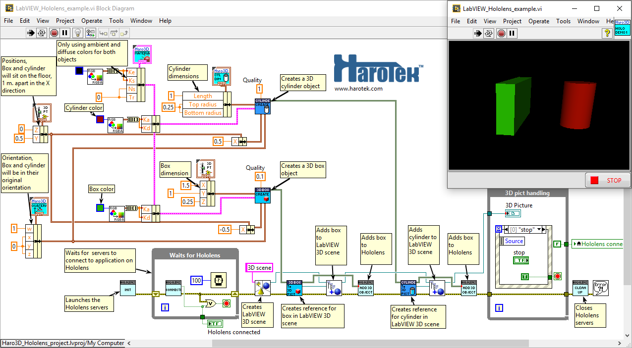
Figure 1 Block diagram of the VI creating and displaying the box and cylinder in both the 3D picture control (shown here in the upper left corner) and in the Hololens (see next figure).
The box and cylinder are created by calling Create.vi corresponding to the desired shape. Intial dimensions, appearance, position, and orientation are passed to Create.vi as parameters. The box and cylinder are instances of classes, as shown in the block diagram of figure 1, derived from the "3D object" class. The box and cylinder objects are simply wired to the to_3DPict.vi and to be Add_3D_object.vi to be displayed in the 3D picture control and in the Hololens. The servers had first to be initialized (Init.vi) and the communication link ascertained (Connect.vi). The 3D pict handling loop simply suspend the execution of the VI for the user to move the point of views from within the 3D picture control and with the Hololens. The Clean_up.vi closes the communication with the Hololens. Figure 2 shows the the virtual box and cylinder within the user environment.
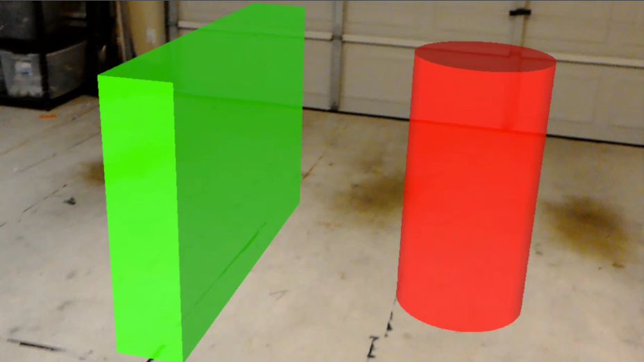
Figure 2 Box and cylinder as seen by the user wearing the Hololens.
Thanks to inheritance and dynamic dispatching, all instances of classes derived from the “3D object” class can be generically displayed in a 3D picture control and in the Hololens like the box and cylinder shown in the block diagram of figure 1. Figure 3 shows mesh objects with textures as displayed in the Hololens using this approach. OBJ-format mesh files were uploaded in LabVIEW using the related functions of the Haro3D library. Thank you to NASA and to Ringo3D for the royalty-free models. (nasa3d.arc.nasa.gov/detail/nmss-z2 and www.turbosquid.com/3d-models/free-heart-3d-model/957963 ).
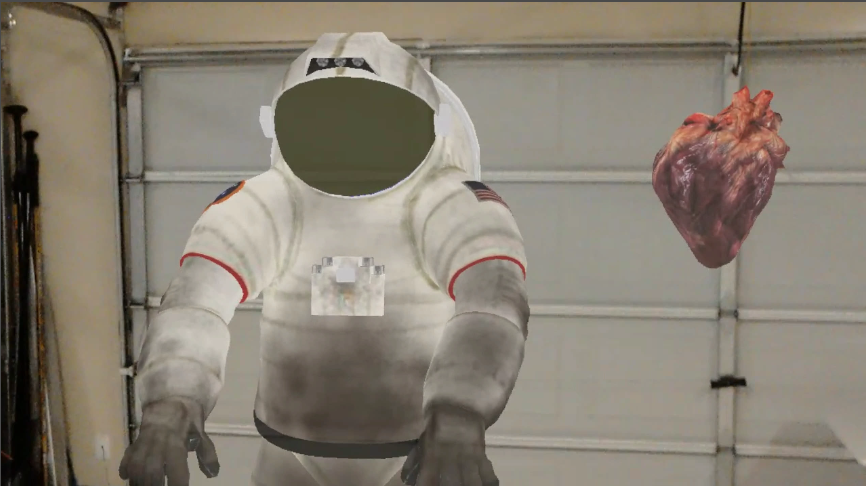
Figure 3 Mesh objects with textures displayed in the Hololens.
User interaction with the Hololens is kept at a minimum. The "air-tap" gesture is used to set the origin point in the actual environment, and the bloom gesture (all fingers of one hand up and opening) is used to terminate the application. It is expected that all other user interactions would be handled by LabVIEW (see coming examples).
The user selects a surface in the actual environment by moving his head. A visible green cursor indicates the line of sight of the user (called gaze by Microsoft). The green cursor is positioned in the virtual environment at a position corresponding to the first surface in the line of sight of the user. The green cursor is therefore the link between the actual and virtual worlds. When air-tapping, the surface currently selected by the cursor is briefly highlighted in blue.
Summary
The toolkit introduced in this document will provide a tool for engineers and scientists that use LabVIEW to explore applications for augmented reality in general, and for the Hololens in particular. Examples of such possible applications will soon be posted.
Please, do not hesitate to post feedbacks here or directly to me.
Marc Dubois
03-09-2017 02:07 PM - edited 03-09-2017 02:07 PM
- Mark as New
- Bookmark
- Subscribe
- Mute
- Subscribe to RSS Feed
- Permalink
- Report to a Moderator
Based on the feedbacks I received from the previous videos, I introduced more interactive features in the LabVIEW toolkit for the Microsoft Hololens. Some of those features are presented in the video below.
The Hololens interface will be part of the Haro3D library version 2.0, soon to be released. Let me know if you have comments or feedbacks.
