- Subscribe to RSS Feed
- Mark Topic as New
- Mark Topic as Read
- Float this Topic for Current User
- Bookmark
- Subscribe
- Mute
- Printer Friendly Page
Autonomous Robot Handling Objects Using the Kinect
02-09-2016 07:41 AM
- Mark as New
- Bookmark
- Subscribe
- Mute
- Subscribe to RSS Feed
- Permalink
- Report to a Moderator
Overview
The application presented here was originally started as a Kinect Hackathon project in Austin, TX back in February 2015. Unfortunately, the project could not be completed within the Hackathon because of hardware issues. The project was completed independently in the following week and a video was posted on Youtube (see below).
A far cry from Skynet, this project consists in a low-cost robot operating autonomously. The application can even monitor if a human is present to supervise the robot operations. The application stops the robot if the human enters the operation zone of the robot.
The 3D cloud data provided by a Microsoft Kinect V2 is used to track objects and the robot in a 3D volume to control the robot that is not equipped with any feedback or servo. In addition, the Kinect ability to track humans is used to detect presence and position of a human.
This application is an example of the ability of LabVIEW to easily combine various technologies.
Video
Description
The robot is a low-cost (less than $50) robotic arm toy, OWI-535. A kit can be separately purchased that provides the ability to control the robot through a USB port. Unfortunately, the USB driver provided with the robot kit is not compatible with LabVIEW. A dll was developed using the OWI-535 communication codes and the Win USB protocol to control the robot from LabVIEW. The VI provided with this document includes the code to manually operate the robot. The details about the driver for that robot along with a demonstration VI is also separately provided in document-46880.
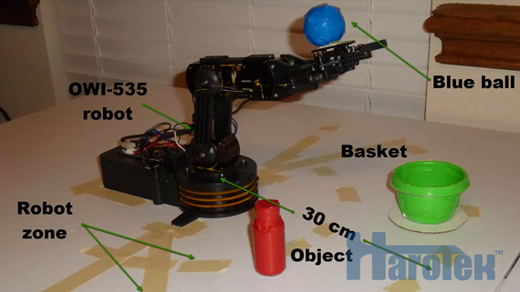
OWI-535 robot, object and basket, and robot operating zone.
The information from the Kinect is obtained using two APIs from the Haro3D™ library: Cloud of points and Bodies. The 3D information from the clouds of points is extracted using the colors. A blue ball (foam golf ball covered with blue duct tape) was glued to the extremity of the robot arm, just behind the gripper (see figure above). The blue ball provides the position information of the robot. The goal of the operation is to put an object (small plastic bottle covered by red duct tape) into a basket (small plastic bowl covered in green tape). The software tracks the robot blue ball, the object, and the basket. The information provided by the Kinect enables the VI to continuously attempts to put the object in the basket, wherever the object and the basked are in the robot operating zone. The VI also determines in real-time if the object and the basket are too close of each other, and if either the object or the basket are outside the robot zone.
Finally, the ability of the Kinect to detect and track humans is used to determine if a human is present to supervise the robot operations. If no human is present to supervise, the robot operations should stop. However, if the human is in the robot operating zone, the robot should stop immediately. A check box was added to to the front panel to enable or disable the requirement for human supervision.
Requirements
Hardware
Microsoft Kinect V2.
Computer meeting requirements for the Microsoft Kinect V2 (http://msdn.microsoft.com/en-us/library/dn782036.aspx).
OWI-535 robot. The OWI-535 was blackened using a marker to prevent any interference with the colors of the tracked objects. Since yellow was not used at the end, the blackening was not necessary. The robot has also been modified to use two 3V power supplies instead of four D batteries (two 3V power supplies are necessary, a single 6V power supply does not work). The light inside the gripper of the OWI-535 was removed to improve the ability of the robot to grip the object.
Software
Software requirements for Microsoft Kinect V2 (http://msdn.microsoft.com/en-us/library/dn782036.aspx).
Haro3D library (downloaded and installed using VIPM).
USB driver for OWI-535 robot (see document-46880).
Installation
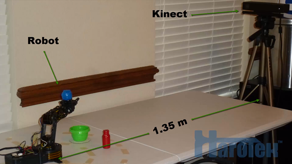
The robot and its zone of operation must be positioned in a manner where the blue ball, the basket, and the red object can be seen by the Kinect. The base of the robot (center of rotation of shoulder) relative to the Kinect must be provided or measured. A robot base calibration function is available from the VI.
On a 8-core I7 3GHz computer, the application is running at about 10 Hz with the 960x540 resolution, and with the 3D View off. There is no benefit using the highest RGB resolution because the depth sensor resolution is 512x454. With the 3D view ON, the rate drops to approximately 6 Hz.
The Kinect sometimes stops providing cloud data. The body data does not seem affected. The problem seems to be related to the overall rate of data. Similar problems were reported elsewhere with the Kinect V2 and might be related to specific USB 3.0 buses.
The basket was filled with small pieces of foam to prevent the bottle to bounce back out.
Below is a picture showing the installation of the robot relative to the Kinect.
VI Operation
The front panel of the main VI is shown below.
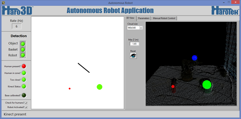
On the left, a series of LEDs indicate the status of the system. At the bottom left, two checkboxes are used to activate the robot operations and to activate the requirement for human presence.
In the center, a 2D picture control shows a top view (XZ plane) of the robot, of the object (red point), and of the basket (green circle). The Robot is shown as a black line, one extremity being the robot gripper (blue ball) and the other extremity (center of the 2D picture control) is the robot base.
On the right is a Tab control with three tabs. 3D View, Parameters, and Manual Robot control.
3D View tab
The 3D View tab (shown below) has a 3D picture control along with the Cloud size enum, Max Z (m), and a Reset view button.
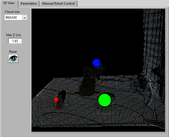
The 3D positions of the objects as determined by the application are shown in the 3D picture control by drawing blue, green, and red spheres, corresponding to the determined positions of the robot gripper, basket, and object.
The Cloud size enum has three possible values: 480x270, 960x540, and 1920x1080. Those values correspond to the resolution of the RGB camera of the Kinect. The depth sensor has a fixed resolution of 512x454. Therefore, the 1920x1080 resolution does not increase the accuracy relative to the 960x540 resolution. Acquisition rate is significantly affected by the resolution.
The Max Z (m) value is the maximum value of Z (Z value in the Kinect coordinate system) that is displayed in the 3D view. The Max Z value affects only the 3D display.
The Reset button sets the view of the 3D display in its default position.
The cloud data is displayed in the 3D picture control only when the 3D View tab is selected. Maximum acquisition rate is achieved when cloud data is not displayed.
Parameter tab
The Parameters tab contain the parameters for the data analysis.
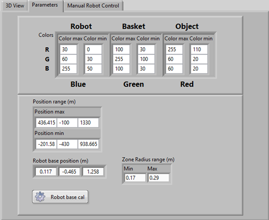
The colors are the ranges of colors for the robot ball, basket, and object given in R,G,B values, each value ranging between 0 and 255.
The Position range (m) is the maximum 3D volume analyzed to find the robot, the basket, and the objects. The position range must include the robot base and the Zone Radius Range.
The Position range and the robot position are given in meters and are relative to the origin of the coordinate system of the Kinect (center of the depth sensor).
It is better to setup the minimum value of the Y range so that if the red object falls on its side, it is out of the range. The value can be easily determined by adjusting the value while switching the object from standing to fallen on its side.
The Zone Radius range (m) is the distance range from the robot base position in the Kinect XZ plane defining a zone where the object and the basket must be for the robot to be able to access them. This is also the zone where the presence of a human stops the operations.
The robot base position is the position of the center of rotation of the robot. This value can be manually entered or measured using the “Robot base cal” button.
Instructions for robot base calibration
Remove the basket from the Robot zone
Put a ball having a size approximately similar to the one of the basket (or the basket itself) on the robot base (shoulder motor of the OWI-535).
Move the robot arm so that the basket (or ball replacement) can be seen by the Kinect. When it is detected, click “Robot base cal”. The position of the green circle is used as the center of rotation of the robot. When properly calibrated, the end of the black line, that is also in the center of the 2D picture control, must be in the center of the green circle. If the robot base or the Kinect are moved, the robot base position must be recalibrated. A correct robot base position is essential for the correct interpretation of the robot movements.
Manual robot control tab
The “Manual Robot Control” tab contains buttons to manually move the robot.
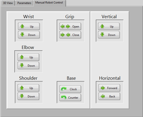
When this tab is selected, the “Robot Activated?” checkbox is automatically unchecked.
Status Window
A status window shows the currently on-going robot operation. The status window is dynamically launched and runs asynchronously with the main VI.

Green indicates that the operation is on-going, red that a problem prevents the operation, and blue that no operation is possible (initialization or main VI terminated for example).
Summary
The project presented here shows how the Kinect can be used for real-time 3D position feedback with relative ease, especially when used in combination with LabVIEW.
Do not hesitate to contact if you have any question about this project.
Marc Dubois
Come join NI 3D Vision group.
