- Subscribe to RSS Feed
- Mark Topic as New
- Mark Topic as Read
- Float this Topic for Current User
- Bookmark
- Subscribe
- Mute
- Printer Friendly Page
3D Anaglyph image generation using LabVIEW
09-16-2015 12:04 PM
- Mark as New
- Bookmark
- Subscribe
- Mute
- Subscribe to RSS Feed
- Permalink
- Report to a Moderator
Overview
It is possible to use LabVIEW to dynamically generate images that can be perceived in 3D using the side-by-side 3D format with 3D TVs and 3D projectors, typically using active 3D glasses (see document 43869).
An alternative to the use of a 3D TV or projector with active 3D glasses is to generate the 3D images in anaglyph format (3D effects obtained by using red-blue glasses). The 3D effects when the images are in anaglyph format can be observed from any color monitor.The dynamic 3D side-by-side images can be saved as a video that can be converted into the 3D Anaglyph using a software or simply youtube. This solution does not provide the ability to interact with the 3D images though.
It is better to directly generate the anaglyph images. This document presents a simple way to generate 3D anaglyph images directly within LabVIEW.
Description
Dodecahedron
To test the dynamic creation of 3D anaglyph images, a relatively complex solid that would benefit from the 3D effects was needed. A simple dodecahedron (solid with 12 faces) appeared as a good choice. The equations used to generate the dodecahedron vertices were obtained from Wikipedia. One sub-VI generates all vertices based on a H value (Dodecahedron coordinates.vi). Depending on the H value, the dodecahedron can be a cube (H=0), a regular dodecahedron (H = 0.618) or a rhombic dodecahedron (H = 1.0). The array of coordinates is sent to two For Loops that draw the vertices as 3D spheres, and the edges as 3D cylinders. The number of edges per coordinates is changed based on the H value (arbitrarily chosen). Those operations are all included in a single sub-VI (Draw 3D dodecahedron.vi) so that the dodecahedron can be easily redrawn for different H values based on the user input.
3D stereo images
The stereo effect is created from two 3D picture controls, one for the left eye and one for the right eye. The cameras of the two 3D picture controls are setup using the Setup Camera invoke node at the same position and looking at the same point, except for a shift in the position along X corresponding to the inter-pupillary distance (see picture below). The 3D dodecahedron is then displayed in each 3D picture control.
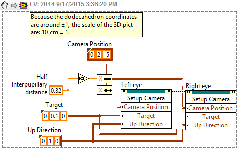
Positions and intializes the cameras of both 3D picture controls for stereo differences corresponding to an inter-pupillary distance of 64mm.
This approach so far is similar to the approaches used for the Oculus Rift document #42169 and for the 3D TV document #43869. The approach in the current project differs from those of the mentioned two documents from here. Two 3D dodecahedrons are created. One red, and one blue. The red one is displayed in the left eye 3D picture control and the blue one is displayed in the right eye 3D picture control.
Anaglyph format
To create the Anaglyph images, the Render to image invoke node is used to extract a 2D image of each of the two 3D picture controls. The color array is then extracted of each of the 2D images and the arrays are "ORed", and then converted back into an image and displayed into a 2D picture control (see picture below).
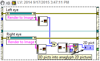
Extracts 2D images from 3D picture controls and combine them into a single 2D pict.
The main VI front panel is arranged so that the 2D picture control can be seen but not the two 3D picture controls (see picture below). Also, it is important that the 2D picture control has exactly the same dimensions than the two 3D picture controls.
Application
The required VI and sub-VI's can be downloaded from this document. The front panel of the main VI (3D Dodecahedron_Main_simple.vi.) can be seen below. The 3D effect can be observed from the image below directly from this document using 3D blue-red glasses (red on the left eye).
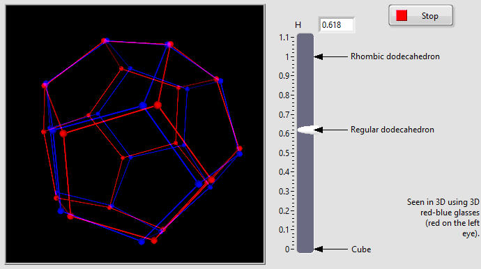
Front panel of the main VI (3D Dodecahedron_Main_simple.vi).
Notice that when looking at the rotating image without anaglyph glasses, the brain can be tricked to see the dodecahedron rotating in either direction. With the glasses, no confusion is possible.
Software requirements
The provided VI sub-Vis were saved in LabVIEW 2014 format. Open and run 3D Dodecahedron_Main_simple.vi.
Hardware requirements
A pair of Anaglyph 3D glasses (red, blue), the red being on the left eye.
Video
A video of the transforming dodecahedron (from regular dodecahedron to cube to rombic dodecahedron and back to regular dodecahedron) was posted on Youtube:
Summary
This document presents an approach to generate 3D anaglyph images directly within LabVIEW. A VI example is provided and shows that the 3D effects work pretty well.
Even though anaglyph images are more difficult to see in 3D than those seen with active 3D glasses, they do no require any special display hardware and the glasses are cheap and can be obtained very easily. These two advantages make the 3D anaglyph attractive in some cases when dynamic and interactive 3D vision is required within LabVIEW.
11-30-2016 07:00 AM
- Mark as New
- Bookmark
- Subscribe
- Mute
- Subscribe to RSS Feed
- Permalink
- Report to a Moderator
Hi Marc
Thank you for sharing.
Unfortunately you can not rotate/zoom/move 3D object by mouse.
Would it falls on LabVIEW 3D Picture bug when you update ModelViewMatrix then whole mouse control is not rotated as it should?
Best regards
Peter
12-11-2016 11:22 AM
- Mark as New
- Bookmark
- Subscribe
- Mute
- Subscribe to RSS Feed
- Permalink
- Report to a Moderator
The Anaglyph image is rendered in a 2D picture control, so there is no mouse interaction by default. This is not a bug.
To create the 3D effect, two 3D Picture controls are used. They can be seen in the front panel if you scroll down. The view in each 3D picture control is controlled so that the view point is different only by the interpupillary distance. The resulting images of the 3D picture controls are rendered as a single in the 2D picture control.
If you want to control the Anaglyph image from the 2D picture control, you can develop the code yourself, using the mouse down event in an event structure for example.
12-13-2016 07:58 AM
- Mark as New
- Bookmark
- Subscribe
- Mute
- Subscribe to RSS Feed
- Permalink
- Report to a Moderator
Thank for replay, but...
I know how your code works.
What I am trying to ask is how to do Anaglyph image where you are able to rotate, move and zoom displayed 3D object.
Would not to be easier to use one of the 3D picture to process mouse events instead of re-implementing it by your-self in 2D Picture?
(And then there is problem: once you update 3D Picture 'ModelViewMatrix' value then mouse control of 3D Picture is not working correctly anymore.)
Peter
CLA
Amfax Ltd.
NI Platinum Alliance Partner
12-17-2016 10:48 AM
- Mark as New
- Bookmark
- Subscribe
- Mute
- Subscribe to RSS Feed
- Permalink
- Report to a Moderator
The way I see it, if one tries to use a single 3D picture control to get an anaglyph effect, two objects would need to be put in the 3D picture control, one for each eye. Each object could be positioned at an offset angle corresponding to the difference in angle perceived by each eye but it would be valid for a single camera position and orientation. There are a couple of problems with this approach. First, as soon as the user would move the object using the mouse, both objects would need to be repositioned, loosing the benefits of using the 3D picture control in the first place. Second, the camera position would need to be extracted from the modelview matrix (camera information is not directly provided by LabVIEW).
It seems to me that the approach I used is easier and more accurate. Mouse control is so easy to integrate. Have a look at the attached files where I implemented the object rotation using the mouse.
