From Friday, April 19th (11:00 PM CDT) through Saturday, April 20th (2:00 PM CDT), 2024, ni.com will undergo system upgrades that may result in temporary service interruption.
We appreciate your patience as we improve our online experience.
From Friday, April 19th (11:00 PM CDT) through Saturday, April 20th (2:00 PM CDT), 2024, ni.com will undergo system upgrades that may result in temporary service interruption.
We appreciate your patience as we improve our online experience.
08-13-2013 02:59 AM
 | This document was created for the myRIO Balancing Robot Project https://decibel.ni.com/content/groups/myrio-balancing-robot |  |
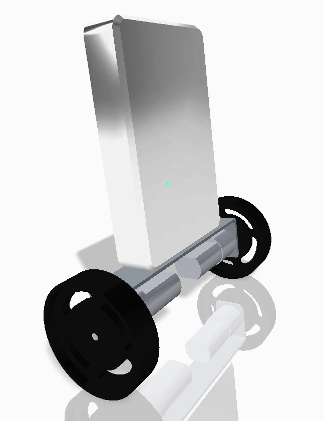
This document describes the CAD Prototype created for myRIO Balancing Robot, according to User Story U-002: CAD Prototype
The CAD Prototype was created using PTC Creo Elements. http://de.wikipedia.org/wiki/Creo_Elements/Direct_Modeling
http://de.wikipedia.org/wiki/Creo_Elements/Direct_ModelingFor the use in LabVIEW a *.wrl File was created. All Elements (wheel1, wheel2, motormount, motor1, motor2 and myrio) of the prototype are accessible as individual parts in LabVIEW.
A rendering "balancingbot.png" has been created and is in use as the group picture for the myRIO Balancing Robot NI Community group.
All documents can be found attached to this document.
![]()
The CAD Prototype was created using PTC Creo Elements. http://de.wikipedia.org/wiki/Creo_Elements/Direct_Modeling
The parts and assembly files are presented in "myRIO_BalancingRobot_CAD.zip" file attached to this document.
The file "myRIO_BalancingRobot_STL_v1.stl" can be used to import the model to other CAD programs, or to print the Prototype on a 3D printer.
The file "myRIO_BalancingRobot_3D_v1.pdf" is a 3D enabled pdf file that can be used to look at the CAD model without the need for specialized software.
LabVIEW needs VRML (*.wrl) files in order to work with 3D-models. To read more about VRML files please read: http://en.wikipedia.org/wiki/VRML
The LabVIEW model was created using the "Save as" function in CREO Elements. The VRML files have been created in the assembly view.
CREO creates a *.wrl file for every part:
balancingbot_v1.wrl inlines all the other files. So make sure, all files are placed in the same location.
The parts are presented in "myRIO_BalancingRobot_WRL.zip" file attached to this document.
The VI "Draw myRIO Balancing Robot.zip" shows a quick example how the Robot can be built inside LabVIEW.
The zip file contains a LabVIEW project, compiled for LabVIEW 2013, showing how to draw a myRIO Balancing Robot inside LabVIEW.
The CAD prototype described in this document serves as a starting point for all Simulation activities (e.g. U-028 Simulate simple balancing Robot).
The CAD prototype contains models of the elements used for the myRIO Balancing Robot prototype (as described here: https://decibel.ni.com/content/docs/DOC-30571). The wheels, motormount and motors are exact models of the original Digilent parts.
The "myRIO" on top of the motormount is a rough representation of the real myRIO device, no mechanical structure to hold the device in place is presented in this work.
For further development additional elements can be placed on a future CAD model, e.g. batteries, sensors, an exact model of the myrio, mechanical structure.
