From Friday, April 19th (11:00 PM CDT) through Saturday, April 20th (2:00 PM CDT), 2024, ni.com will undergo system upgrades that may result in temporary service interruption.
We appreciate your patience as we improve our online experience.
From Friday, April 19th (11:00 PM CDT) through Saturday, April 20th (2:00 PM CDT), 2024, ni.com will undergo system upgrades that may result in temporary service interruption.
We appreciate your patience as we improve our online experience.
06-24-2015 06:01 AM
Hi Brian!
Currently, I am defining the concepts to develop a Hardware-in-the-loop system for an ECU (ABS). The main target is to use HIL simulation technique inside universities, so the students can learn more about automotive systems. I'm trying to find the best solution to build-up the interface between the ECU HW and the Simulation SW (Vehicle simulator) and NY MyRio seems to match the project requirements. As I don't have the experience with NI platforms, I'm not 100% sure whether MyRio can be used for HIL simulation. I took a look in several different articles about HIL simulation using NI platforms, but all of them used PXI platform.
Could you please help me with this topic?
Best Regards from Brazil,
Junior
06-24-2015 11:45 AM
Hi there,
I'm happy you asked about HIL simulation on MyRIO. I created an FPGA-based HIL simulator application for MyRIO back in 2013 and I'm not sure if I ever published the code on this forum. Since it runs on MyRIO and it's extremely fast, it actually must be one of the lowest cost, highest performance real-time HIL simulators "on the market."
It runs on MyRIO and achieves 5.7 MHz (175 nanosecond) timesteps for a first order system, 3.07 MHz (325 nanosecond) timesteps for a second order system, 2.1 MHz (475 nanosecond) timesteps for a third order system, etc. Rate [Hz] = 5748304.29*ORDER^(-0.917)
The way it works is by creating a floating point real-time transfer function simulator "server" that can simulate N number of independent or coupled transfer function "channels" by storing in FPGA RAM the numerator and denominator coefficients, inputs and outputs, and state-information for each channel. The transfer function solver "server" runs in a single cycle timed loop (SCTL) at 40 MHz, and takes Y clock ticks to update the state and output information for each channel, where Y depends on the order of the transfer function. (If TF_Order=1, then Y=7 ticks. If TF_Order=2, then Y=13 ticks, etc.)
Because the transfer function inputs and outputs are stored in FPGA RAM, it is relatively easy to interconnect the transfer functions in series, parallel, or feedback paths (with linear or non-linear math equations that define the coupling relationships using the IP cores in my floating point toolkit library) and thereby build up the simulation model for a large system simulation with N number of transfer functions.
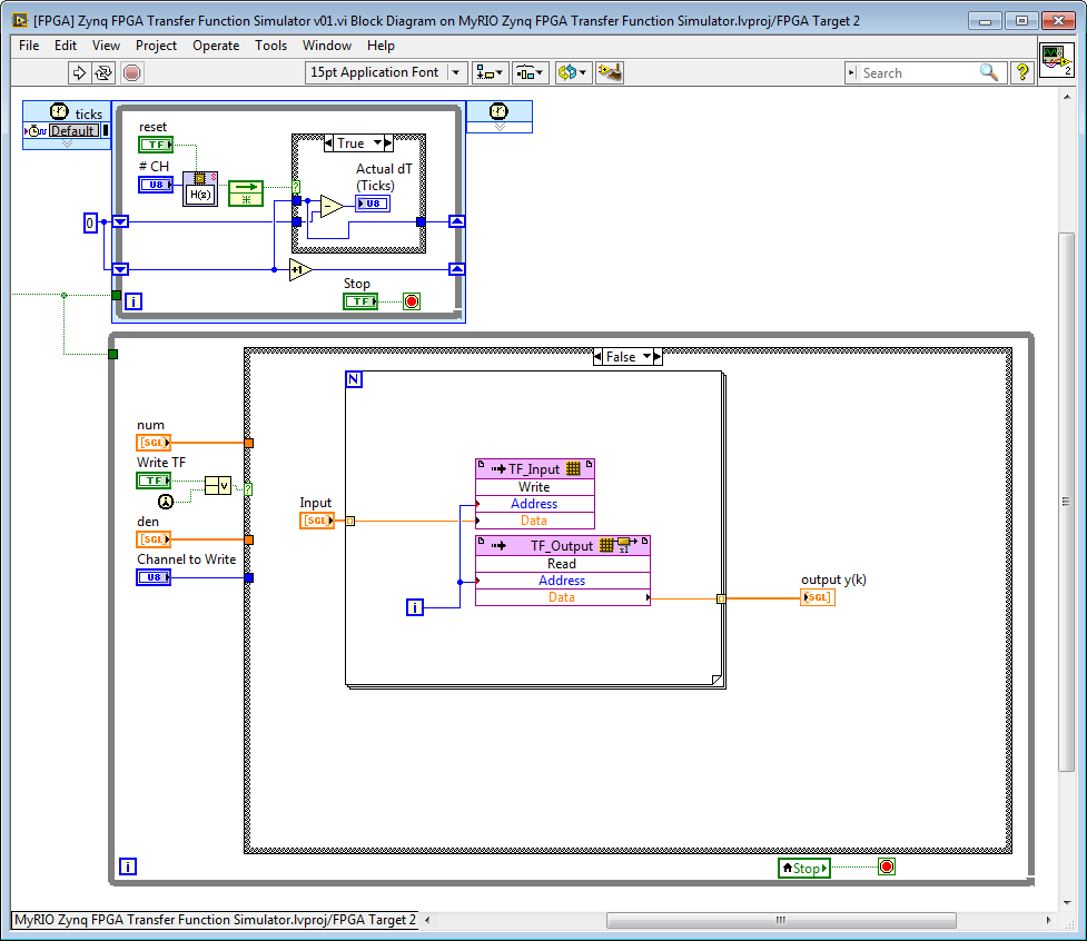
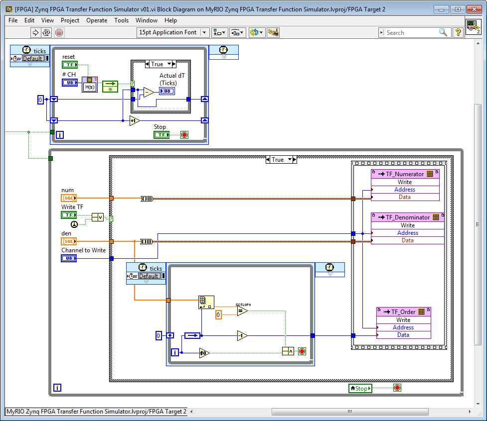
Below is a screenshot showing a simpler case of 16 independent transfer functions. Even though the MyRIO Zynq 7010 FPGA is small, this compile only takes 80.4 percent of the FPGA Slice LUTs, so there is still quite a bit of room left to add floating point math equations that define the custom interconnection relationships between the transfer functions. In the screenshot below, the upper loop is the "multichannel simulation solver server" and the lower loop defines the input/output relationships between the transfer functions. (In this case, they are all independent and there is no coupling.) We should probably run this "transfer function interconnect" code in it's own loop.
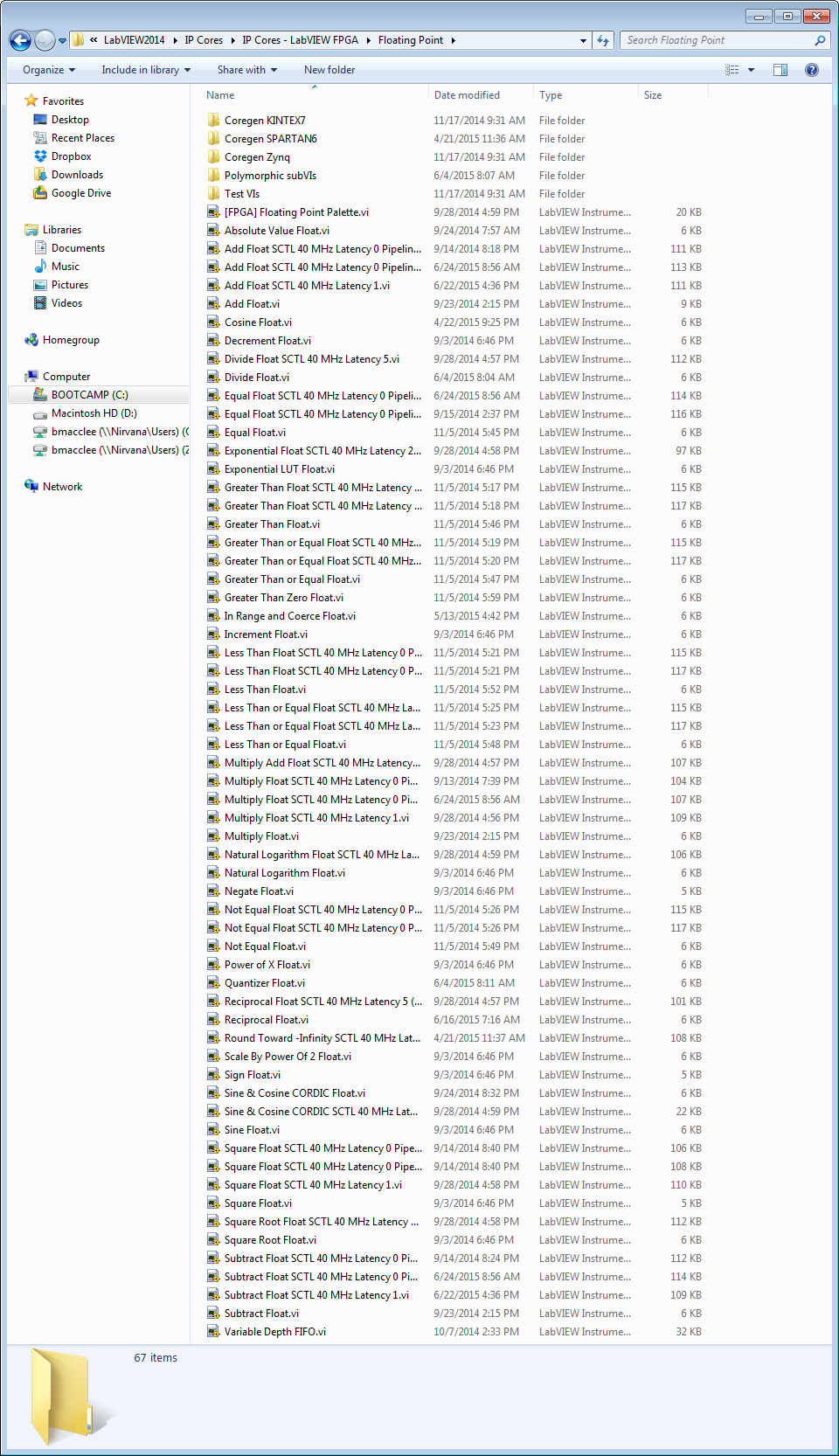
To define custom interconnection math that defines the relationship between the transfer function channels, you can use the (non SCTL) IP cores in my floating point math toolkit (..\IP Cores\IP Cores - LabVIEW FPGA\Floating Point). As you can see, it's become quite a full featured library of floating point IP cores. To learn how to use it properly, read this whitepaper (
). Note that although the transfer functions themselves are linear, there is no requirement that the interconnection between transfer functions must be linear.
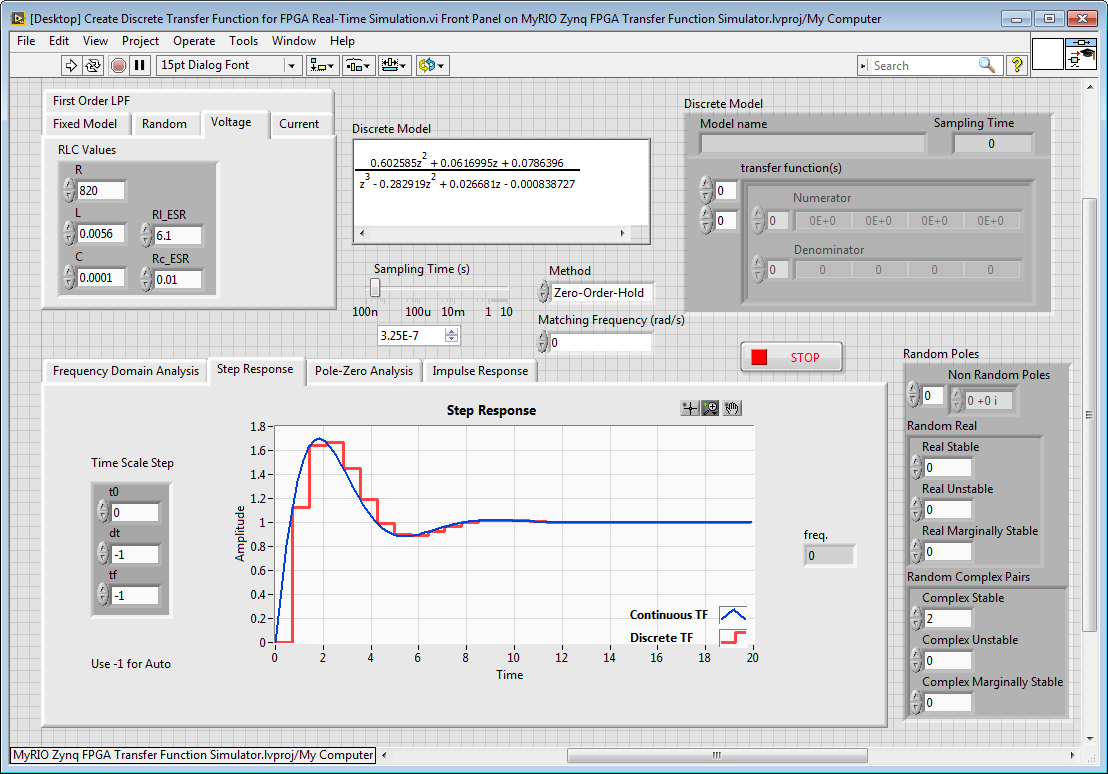
The lower loop is also used to write the transfer function numerator and denominator coefficient values. Note that I implemented a discrete time (z-domain) transfer function solver rather than a continuous time (s-domain) solver, so I use the "CD Convert Continuous to Discrete.vi" from the NI Control Design & Simulation Module to convert the transfer function to discrete form before loading into the FPGA.
There is a desktop application included in the project that demonstrates how to perform the continuous to discrete conversion, and sends the transfer function models to the MyRIO RT application using shared variables, which then loads them into the FPGA.
You can download this 'open source' MyRIO application from here. You must unzip in a short path (i.e. C:\MyRIO\..) and not your desktop because the Xilinx Coregen files in the IP library have long directory paths.
BTW, we should probably start a new discussion thread for this topic. Let me know if you need any help writing the code to interconnect the transfer functions for your simulation model, or if any other questions come up, and please share back screenshots if/when you get your first model running.
06-26-2015 06:03 AM
Hello Brian!
Thank you very much for your very detailed explanation. As soon as I have the first results I'll create a new topic to discuss it and to share my experiences.
Best Regards!
07-17-2016 11:37 PM
Where to purchase the add on board?
08-08-2016 11:07 AM
This open source design is still in development and is looking for someone to complete it.
Big thanks to a student at the University of Texas Center for Electromechanics (http://www.cem.utexas.edu/) for doing the most recent set of updates and improvements to the design, which include a built in PCB mount LC line reactor filter and other updates. The idea is that students should be able to connect their boards together to form a microgrid simply by wiring the three phase terminals to each other. Very exciting!
Attached are the latest Multisim/Ultiboard design files and bill of materials (BOM) for the MyRio Mini-inverter.
Here are notes on what work remains to be done:
"The floating grid and phase voltage inputs for the 0..5 V unipolar ADC of the MyRIO still need to be addressed. This can be done using Analog Devices AD628 difference amplifiers and a 2.5v voltage reference like the REF192. These part numbers in the BOM but the circuit design has not been implemented."
Is anyone willing to volunteer to complete this design?
08-28-2017 06:12 AM
