From 04:00 PM CDT – 08:00 PM CDT (09:00 PM UTC – 01:00 AM UTC) Tuesday, April 16, ni.com will undergo system upgrades that may result in temporary service interruption.
We appreciate your patience as we improve our online experience.
From 04:00 PM CDT – 08:00 PM CDT (09:00 PM UTC – 01:00 AM UTC) Tuesday, April 16, ni.com will undergo system upgrades that may result in temporary service interruption.
We appreciate your patience as we improve our online experience.
01-22-2013 10:00 AM
Hi Muruganandhan,
I recreated your circuit in Multisim and tried to just run it using a transient simulation (without LabVIEW, as a first troubleshooting steps). There are a few you have to consider when designing an IGBT inverter:
- Drive the IGBTs with the correct votlage level, for these IGBTs you need at least 12V at the gate
- Take fall and rise time of your switching in consideration so you don't run into transient time simulation singularities
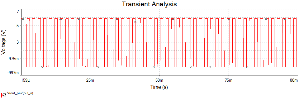
I attached the test file I ran in Multisim, it is fixed and the inverter is working (check below). In order to review your control loop in LabVIEW, as I mentioned before, I need to take a look at your actual file. Please send it over.
Thank you.
Mahmoud
01-22-2013 11:36 AM
Thank you for your quick reply. The information which is given in your previous post was very useful for me. I have attached the files below. kindly review it and notify the errors.
10-24-2013 03:20 AM
Hi, Mahmoud
I have LabVIEW x32 and Multisim 13.0. I have the same problem as Ahmed:
"Control Design and Simulation: The shared library corresponding to the external model returned an error.
Unable to load library"
But I have the Control Design and Simulation installed already.
I did the circuit of this tutorial:
http://www.ni.com/white-paper/13663/en
When I put the Multisim file into LabVIEW, I can't expand the file to view to see the pins of it.
As you can see in the figure, the pins of the multisim file don't appear on LabVIEW. Also, is there a problem of the LabVIEW and Multisim version? Because my computer is x64 and LabVIEW is x32, but the program worked just fine. Can you help me?
11-10-2013 04:45 PM
It seems that this error always happens in co-simulation. I just built a very simple H bridge model. And the driving signals from labview were provided to un-ideal MOSFETs (built a new Infineon spice component) through voltage controlled voltage source. The load was just a resistor. When I ran the simulation, it takes very long moment to finish 0.02s simulation (fsw=50000Hz). If I changed the step size, there will be the same error.
11-11-2013 10:18 AM
Can you attach the Multisim file please? The first thing to do is determine if it's a problem with the custom SPICE component model you created or something else.
Note: You want to first test by running the simulation in Multisim alone, without the co-simulation interface-- get it working standalone first.
If it's not a problem with your custom SPICE model you created, then here are some suggestions:
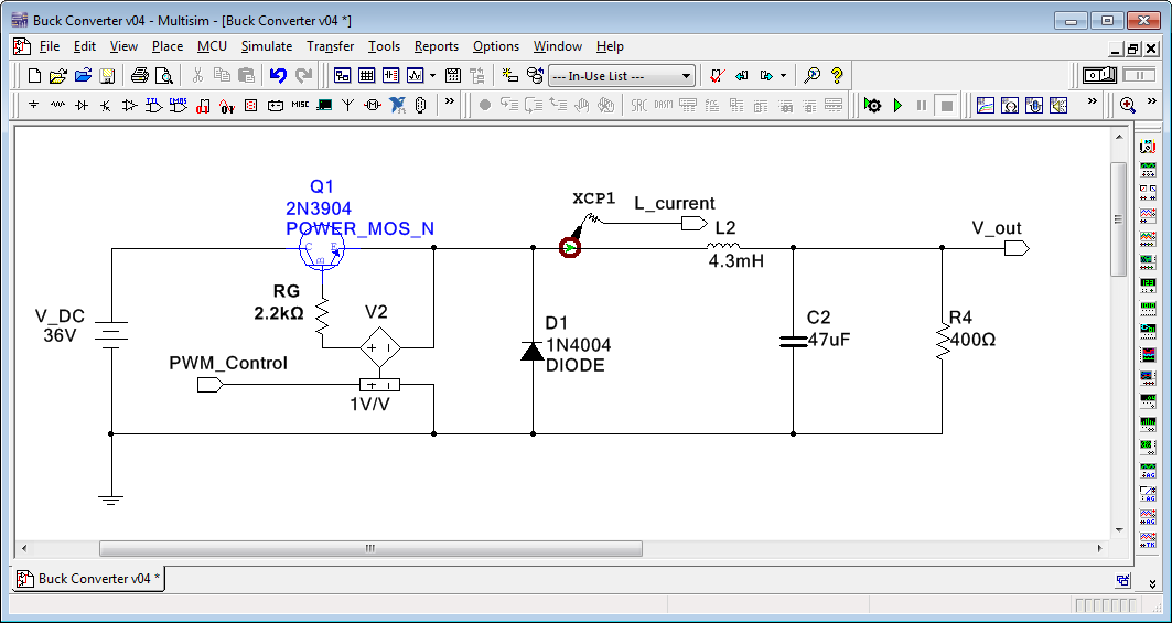
First, read through the suggestions above in this thread. Most likely there is a problem such as a floating signal- you need to ground the load resistor perhaps. Or you might have two sources driving the same signal. When you are using the vendor models, you typically need to control the voltage between the gate and source using a voltage controlled voltage source controlled by the co-simulation node (right-click on schematic>Place on Schematic>Hierarchical Connector>DIrection:Input>Co-simulation Type:Voltage). See screenshot below for an example.
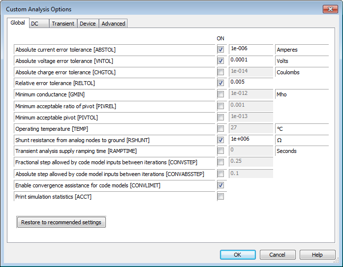
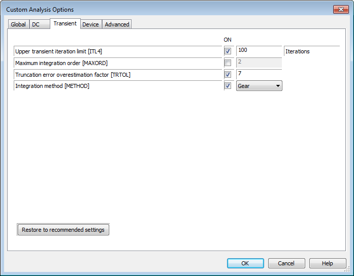
Next, make sure your Multisim simulation settings are appropriate for a power electronics simulation. The default settings are for microelectronic simulations and are not appropriate for power electronics. To do this, navigate to Simulate>Interactive simulation settings>Analysis options>SPICE options>Use custom settings>Customize...
On the Global page, here are some recommended settings for power electronics:
Then on the Transient tab, make sure the Integration method [METHOD] is set to Gear.
11-11-2013 03:18 PM
Please check my uploaded files. The switching frequency is 50000Hz and the frequency of sin is 60Hz. The problem is that if I just connect the resistor to the output of H bridge, it works. But If I add the LC or LCL filter, there will be too small timestep errors.
11-11-2013 04:57 PM
Hello,
I've fixed the problem. The problem is that I didn't save the Multisim files on the Circuit Design 12 directory (this is created by the program during the installation). When I saved the file on this directory and put into LabVIEW, the problem didn't show anymore. Thank you for your help icedancer and BMac
11-12-2013 09:06 AM
Icedancer,
The problems you are having are due to the custom SPICE model you created. You'll need to debug that SPICE model. Actually, I'd recommend using the new MOSFET_DIODE_THERMAL model that was added to Multisim 2013 to enable you to create your own model using information on the vendor datasheet that's much higher performance than a SPICE model but captures the fundamental electrical and thermal behavior of the devices including conduction and switching losses.
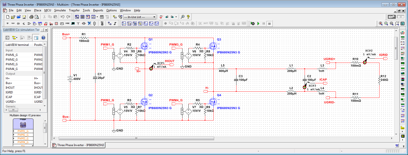
Backing up a bit... To confirm the problem is with your custom SPICE model, I created two versions of the inverter schematic. One has an Infineon transistor model that ships with Multisim (IPB600N25N3). If you replace your custom model with that one, the simulation performs correctly, as shown below.

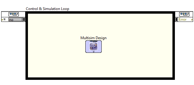
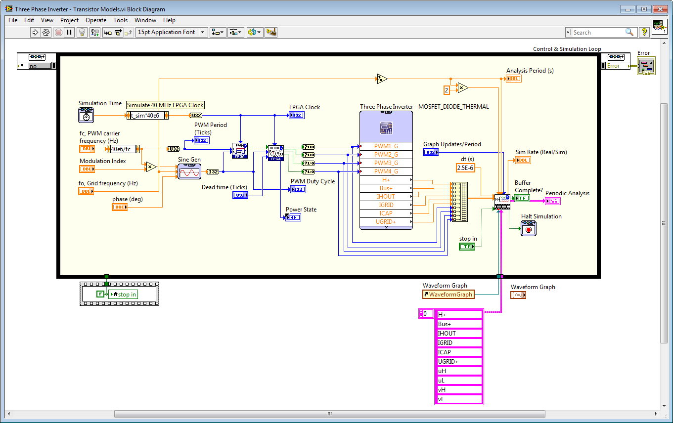
One thing I noticed in your co-simulation VI is that the discrete execution timing was not set for the FPGA subVIs. To set it, right-click on the subVI and navigate to SubVI Node Setup>Discrete and set the period in seconds. I set it to 2.5e-7 seconds, which is appropriate for a 4 kHz carrier frequency. I also replaced your simulation waveform charts with a new n-channel collector IP core, which yields higher simulation performance, automatically logs the simulation results to a TDMS file for post-processing, and facilitates analysis of the simulation waveforms.
Note that since all of the important blocks in the control design & simulation (CD&Sim) loop are discrete (you are not doing any continuous time modeling in the CD&Sim loop), I set the CD&Sim loop to use a discrete time solver with a step size of 2.5E-7 s.
.png)
Note that the preferred way to do these simulations in LabVIEW 2013 is to use the new Desktop Execution Node, which interfaces to your FPGA VI in the project and lets you put it into simulation mode while using the timing primitives in the loops. Then to deploy the same application, you right click on the FPGA target and change the execution mode. You can read and write all of the I/O nodes and front panel controls and indicators and connect the FPGA to Multisim or SimPower Systems for closed loop co-simulation.
Okay, now getting to my recommendation of using the new Multisim 2013 MOSFET_DIODE_THERMAL model. We put a lot of effort into creating this (along with IGBT and Diode variants) because it has been one of the top requested features. It lets you avoid needing to have a SPICE model, which are not available for many high power modules, while capturing the most important device behaviors based on information you type in using the vendor data sheet or using your own device curve tracer measurements.
This can be co-simulated of course with the LabVIEW FPGA code to get a good estimate of system performance based on the actual closed-loop control logic and PWM scheme and the device curve trace data-- excellent for analyzing component selection and performance expectations before building a power converter. We did some clever work to initialize the thermal network correctly for any arbitrary converter topology. You run 1-2 cycles and we can automatically store the power dissipation in each of the switches. Then you restart the simulation and it's automatically initialized to the DC operating point for the thermal network. Otherwise you might have to run the simulation overnight to get the transient temperature simulation to reach steady state.
Below is the schematic with the MOSFET_THERMAL_DIODE model.
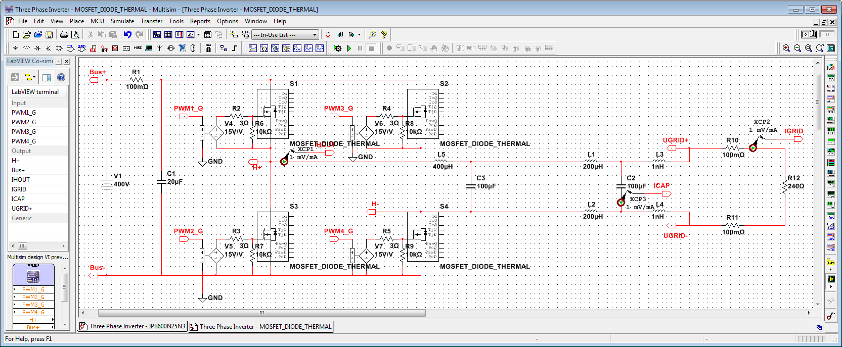
I didn't type in all the data from the vendor datasheet. I'll leave that for you to do. But I did fill in some of the basics.

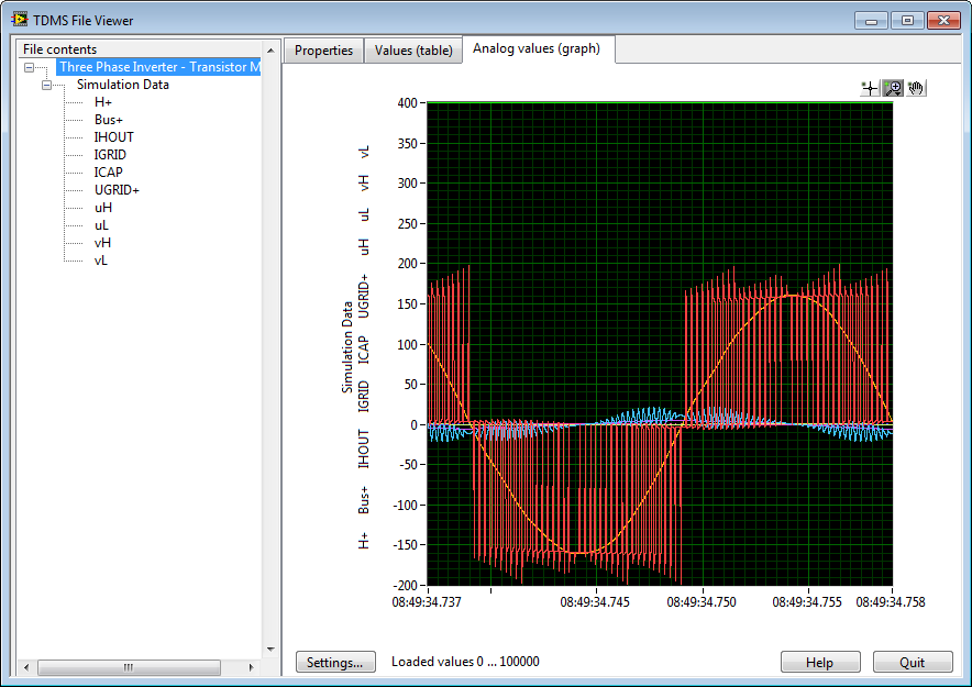
Here is a simulation run with the MOSFET_DIODE_THERMAL models. Note that the simulation speed is 565 times slower than real-time, compared to 5590 times slower than real-time for the Infineon device physics-based SPICE model. That's roughly a 10X speed improvement. However, of course, the thermal model is not as detailed as a vendor SPICE model.
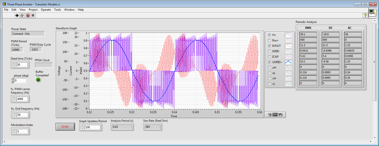
Note that when you stop the simulation, the TDMS File Viewer automatically opens to show you the automatically logged file with all of the simulation results. The log files are automatically stored in your Documents>LabVIEW Data directory. NI DIAdem is an ideal tool for post-processing analysis. The idea here is that you log your test data the same way, from the very first day of the design when you are working in co-simulation and writing your FPGA-based control system, to your field deployments on the NI sbRIO General Purpose Inverter Controller (GPIC) or CompactRIO, to your real-time hardware-in-the-loop (HIL) simulations for comprehensive validation and verification of the control system. It's important, for example, to be able to explain the reasons for any differences between simulation results and physical measurements to ensure that all the design assumptions and rules that the inverter design is based on are actually valid.

You can find all of the LabVIEW code and Multsim schematics shown above here.
11-12-2013 02:14 PM
Thank you so much for your explanation in detail and early reply. I will check them step by step and compare with my original one to try to understadn the whole things.
Here, I have a question. You said that the spice model can be a possible problem. But if I use the same model and connect a resistor to the output of H bridge( without filter), the waveform looks reasonable (just like the theoretical one). So if there is something wrong with the spice model, how can I get the reasonable waveform?
Actually, at first I also thought it may result from the spice model. But when i saw the waveform mentioned above, I figured that the spice model worked fine.
11-12-2013 04:27 PM
One more question. In your feedback, IPB600N25N3 is used to compare with my own-built spice model. But the voltage rating of MOSFET is 250V and my input voltage is 400V. Can I use this spice model?
