From 04:00 PM CDT – 08:00 PM CDT (09:00 PM UTC – 01:00 AM UTC) Tuesday, April 16, ni.com will undergo system upgrades that may result in temporary service interruption.
We appreciate your patience as we improve our online experience.
From 04:00 PM CDT – 08:00 PM CDT (09:00 PM UTC – 01:00 AM UTC) Tuesday, April 16, ni.com will undergo system upgrades that may result in temporary service interruption.
We appreciate your patience as we improve our online experience.
11-12-2014 03:11 AM
Just sharing a small "trick" about configuring the FXP format for an output
This can save some time, especially when you have many values from VeriStand
11-12-2014 05:13 PM
Hi Ryan,
Thanks for all the help, I was able to get everything to work. I wanted to jot down what I found so other newbies like me can learn.
Also kudos to Mathieu for his post, I found that very useful in how to get FXP info from a device.
So for the AI (9205) reading the same on all channels, it helps to have the right COM wire connected. I was using two independent power supplies and was referencing the wrong one to the module. As far as the FPGA code, leave as calibrated and FXP to the XML Buider, set the scale as 1.
For the Analog Outputs, I tried to use them as Calibrated instead of Raw and FXP, I had the FXPWL and FXPIWL incorrect since I didn't know about Mathieu's trick. I then switched the modules to Raw and output them as I16 (+/-10V) and U16 (0-20mA) and set the scale to 10 and 20 respectively. This allowed all analog outputs to work.
I had a quadrature output from a 9411 module that was an I32 to hold the count. I had to scale this to 2147583647 for it to work.
Also if you want to run the FPGA code while VeriStand is running, there is some addition to Ryan's procedure:
Have the RT Target containt he IP address, but don't connect using the RT Target. Under FPGA Target, Execute on FPGA. Under FPGA Targe-> Properties -> General, the Resource must be listed (i.e. RIO0).
Thanks to a great community for the support!
01-12-2015 01:33 PM
Hi Ryan,
I created a Veristand Custom FPGA project and added 2 PWM measurements & 4 PWM outputs. After generating the .fpgaconfig under ./NI VeriStand 2014/FPGA and loaded it in Veristand, an error-7 poping out shows that the corresponding .lvbitx file is missing. But if I generate the .fpgaconfig file under ./NI Veristand 2013/FPGA and load it, a different error-2628 saying that it has issues parsing the document. Does this node work with Veristand 2014?
Thanks
Jian
01-12-2015 01:49 PM
Hey Jian,
Yes, the node is compatible with VeriStand 2014.
The error 7 you're receiving in VeriStand 2014 doesn't have anything to do with the node, but rather is VeriStand saying that based on the XML you've provided, it cannot find your bitfile. So, if you look in the <Public Documents>\National Instruments\NI VeriStand 2014\FPGA directory, do you see your bitfile "My Bitfile_3.lvbitx"? If not, then move your bitfile into that folder. If "My Bitfile_3.lvbitx" isn't what you've named your bitfile, then you'll want to change the name in the node configuration screen and regenerate the XML.
As for the error 2628 when you placed the XML in the VeriStand 2013 directory, those errors also have nothing to do with the node but rather indicate that VeriStand cannot find the necessary schema and defintion files to read the XML file. Overall, if using this in VeriStand 2014, you shouldn't be saving in the VeriStand 2013 directory since it won't find the necessary files.
Hope that helps!
--Ryan_S
01-12-2015 03:23 PM
Hi Ryan,
I placed the lvbitx file under 2014/FPGA folder and it can be loaded into VS now. However, the deployment is not successful if I add this FPGA target. The log from Veristand says that it is because the FPGA is in FPGA interface C API mode, while the console shows an error-1026:VI reference is invalide.
Please note that I am also using engine simulation toolkit which requires a lvbitx file as well. And the project directory between EST and the newly added FPGA target is not the same. The EST includes two CAN modules and EtherCAT module but it does not have the DMA write or read. Will that be the issue?
----------------------------Updated on 1/13/2015------------------------------------
I just created a new project with only the FPGA added. It shows an error-0xFFFF0928 saying that the supplied resource name is invalid. But that name was discovered by LabVIEW itself when creating the project. Do you know where is the problem and how to solve it?
------------------------------------------------------------------------------------------------
Thanks
Jian
01-13-2015 10:08 AM
Hey JianZ,
You are correct, having the two bitfiles separately (deploying to the same FPGA target) is going to cause problems. You'd want to combine those and verify with the engine simulation support that combining them and adding both the engine simulation custom device and FPGA item will work.
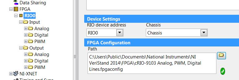
As for the error you're receiving when adding just this bitfile, that could be a configuration issue within your system definition file. If you look at your added FPGA item, you'll want to ensure that the RIO device address/name match the naming convention within MAX.
However, the errors you're receiving are not specific to this add-on. If you continue to encounter these errors I'd recommnd you contanct your local support.
Hope that helps!
--Ryan_S
02-03-2015 10:26 AM
Hi
We kept using this node, latest version (1.1.1.41). Sometimes with failures, that we don't manage to explain
Today for example, we keep getting the following error:
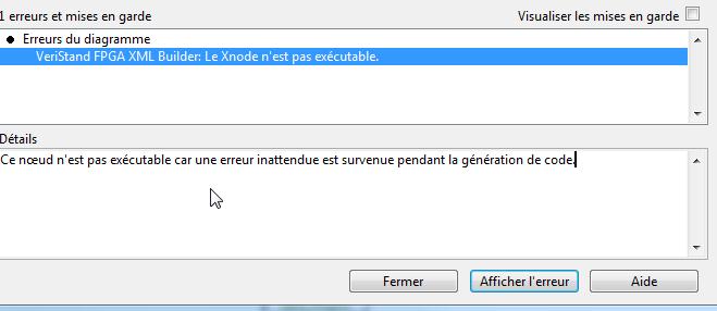
Which means that an unexpected error happened during code generation.
Generated code is actually broken due to lowerleft part of the code not being finished (this is an extract of the navigation window of the generated code)
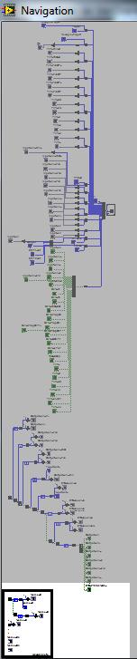
Here is the generated code whose generation is not complete:

There is no error file associated to this uncomplete code generation in C:\Users\thisismydirectory\Documents\LabVIEW Data
Any clue ?
Thanks in advance
02-03-2015 10:32 AM
Me again.
Creating a separate post for this one since it's a suggestion
It would be really helpfull to be able to directly wire clusters to this node
Thanks
02-03-2015 10:34 AM
Hey Mathieu,
It doesn't look like your pictures uploaded properly (or at least they're broken in my view). Can you re-post them and/or attach them to your post? Can you also attach the your VI with the FPGA XML node in it so that we can see the exact configuration that is causing this behavior?
Thanks! --Ryan_S
02-03-2015 10:35 AM
Ryan
Guess you posted right before i was done editing
Could you confirm it's ok now ?
Edit: Can't really attach my VI here in a public section. One can get in touch by mail if necessary
