- Subscribe to RSS Feed
- Mark Topic as New
- Mark Topic as Read
- Float this Topic for Current User
- Bookmark
- Subscribe
- Mute
- Printer Friendly Page
VeriStand FPGA XML Builder Node Feedback
11-01-2016 10:57 PM
- Mark as New
- Bookmark
- Subscribe
- Mute
- Subscribe to RSS Feed
- Permalink
- Report to a Moderator
Hi Ryan_S,
Thank you for your support. According to your tips, I did some tests, the test results are as follows.
1) When i create a new VI and configure it with just a couple inputs, the same problem does not appear.
2) After I romoved the several PWMout node, the Run button becomes normal, but when I click the ”Accept Changes &Generate XML”, then prompts an error so that it can not generate an XML file.
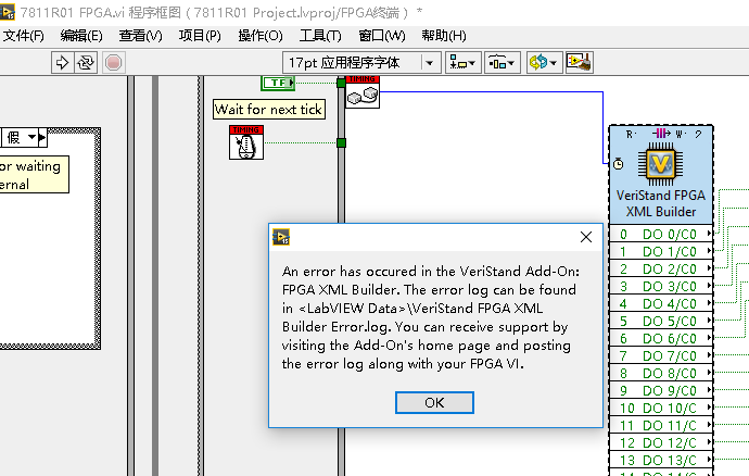
Please see the relevant project” 7811R01” about this phenomenon.
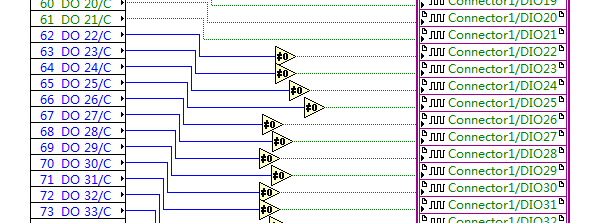
3) When the number of DO exceed 64,the Run button becomes abnormal, but can generate XML file.
Please see the relevant project” 7811R02” about this phenomenon. In this project, if you remove “Output_66” and Connector1/DIO24, the whole program will become normal (the Run button is OK, also can generate XML file)
By, the way, now our project is anxious to use 7811R, can you help us generate XML file and FPGA Bitfiles on your computer. We need the configuration is PXI-7811R(Connect0 0-39 DO;Connect1 0-39 DO;Connect2 0-9 PWM OUT, 10-14 DO;Connect3 0-22 DI,23-39 DO).Thanks!
Best regards
Ning
11-02-2016 06:19 PM
- Mark as New
- Bookmark
- Subscribe
- Mute
- Subscribe to RSS Feed
- Permalink
- Report to a Moderator
Hey Ning,
Well done on the troubleshooting!
It turns out you're the first person to try and send more than 64 boolean channels from VeriStand to the FPGA using this node. There is a bug in how we're scripting the code that isn't properly handling having more than one packet worth of booleans. As for the XML generation error you were hitting, that is likely Known Issue #5 on the node overview page.
I've added this bug as Known Issue #6. I've also listed several possible work-arounds you can use.
If you have questions on the work-around options, or how to implement one of them, let me know.
Hope that helps! --Ryan_S
11-03-2016 07:39 PM
- Mark as New
- Bookmark
- Subscribe
- Mute
- Subscribe to RSS Feed
- Permalink
- Report to a Moderator
Hi Ryan_S,
According to your suggested solution“Known Issue #6/Workaround Option #1”,I have solved this problem.Thank you so much for your help.
Best regards
Ning
01-13-2017 02:26 AM - edited 01-13-2017 02:28 AM
- Mark as New
- Bookmark
- Subscribe
- Mute
- Subscribe to RSS Feed
- Permalink
- Report to a Moderator
Hello,
I built a model, one part of it is converted to a dll file and further put into veristand, another part of it is converted to vhdl file and further put into FPGA CLIP. The two parts of the model send its data to another through this Veristand FPGA XML Builder. Although no error comes out, the simulation results are wrong (for example, correct wave, but wrong amplitude). That's to say, some data transmission mistakes emerge with this XML Builder node. Maybe I didn't use this tool correctly and wonder if you know why this happens.


Best Regards,
Yang
01-13-2017 10:17 AM
- Mark as New
- Bookmark
- Subscribe
- Mute
- Subscribe to RSS Feed
- Permalink
- Report to a Moderator
Hey Yang,
I think I see your issue; specifically, the Fm input isn't set to the correct data type so you're likely getting coercion issue with your data. Normally, the node can look at the input wire to determine its datatype. However, unfortunantely, feedback nodes mask this data type. So, as you'll notice, there's a coercion dot on the input connection to Fm.
To fix that, left click on the Fm line and set the input to be of the "Fixed Point" type. Then go into the node configuration and set the word length and integer word length of your fixed point input. Finally, click "Accept Changes and Generate XML" to re-script the backend code and XML for the fixed point datatype. Then try compiling that and using it in your application.
Let me know if that doesn't fix the issue. --Ryan_S
01-14-2017 04:36 AM
- Mark as New
- Bookmark
- Subscribe
- Mute
- Subscribe to RSS Feed
- Permalink
- Report to a Moderator
Hi, Ryan_S
The problem still exists. I guess our data transmission is a little complicated.
This time we set parameter "Fm" and "v" of XML Builder to fixed point and correspondingly modified the configuration file. But the fixed point parameter "Fm" and "v" in XML Builder need to send data to and from the other part of Veristand project—the dll file, which is compiled from a simulink model, whose data typle is double.
We tried to add two "data type conversion" block in simulink model, hoping "double in simulink(v), then fixed point in veristand(v), fixed point in XML Builder(v), through the FPGA CLIP, then fixed point in XML Builder(Fm), fixed point in Veristand(Fm), finally double in simulink(Fm)" could be realised.
But the results are wrong. I think I need your help.


Best regards,
Yang
01-16-2017 09:07 AM
- Mark as New
- Bookmark
- Subscribe
- Mute
- Subscribe to RSS Feed
- Permalink
- Report to a Moderator
Hey Yang,
Can you simplify the FPGA code to make sure the problem is with the node and not with the model? I.E. If you loop back v to Fm through the feedback node, do you see that data properly in VeriStand? If not, can you post the simplified FPGA code so I can take a look?
Thanks! --Ryan
01-16-2017 09:43 PM
- Mark as New
- Bookmark
- Subscribe
- Mute
- Subscribe to RSS Feed
- Permalink
- Report to a Moderator
Hi, Ryan
As you said, I built a simple model and loop back "v" to "Fm" directly. This time the results are precisely correct. So I think this tool is OK and really great.
But once I add some simple FPGA code between "v" and "Fm"(which is converted from Simulink and the model is proved correct in Simulink), the results are wrong. So I think maybe the problem resides in data type conversion, that is to say , "int32 of XML Builder" to "FXP of FPGA code" and in reverse.
Best regards,
Yang
01-17-2017 08:48 AM
- Mark as New
- Bookmark
- Subscribe
- Mute
- Subscribe to RSS Feed
- Permalink
- Report to a Moderator
Hey Yang,
Hmm, well if the loopback worked then I have to think it's something about the intermediary code. I assume you used the same data types in both the loopback and the node test, which then wouldn't make sense for the loopback test to work and node test not to if it was an issue with the node.
However, keep in mind that you can also test this by bitpacking and writing to VeriStand's DMAs directly (basicaly circumvent the node). This is discussed in the VeriStand help here.
Hope that helps! --Ryan
03-09-2017 08:27 PM
- Mark as New
- Bookmark
- Subscribe
- Mute
- Subscribe to RSS Feed
- Permalink
- Report to a Moderator
Hi Ryan_S,
I want to control frequency and duty cycle generating PWM at run-time.I'v read your Huazy responce.
I want to use the RIO Library and the FPGA XML node to achieve this function
(for PWM Out and PWM In ).
The attachment is my source code,Can i achieve this function?

Looking forward to your reply.
Best regards
Ning
