- Subscribe to RSS Feed
- Mark Topic as New
- Mark Topic as Read
- Float this Topic for Current User
- Bookmark
- Subscribe
- Mute
- Printer Friendly Page
Single DAQ task, six channels, RSE and Differential modes mixed
10-17-2014 03:36 AM
- Mark as New
- Bookmark
- Subscribe
- Mute
- Subscribe to RSS Feed
- Permalink
- Report to a Moderator
Hi,
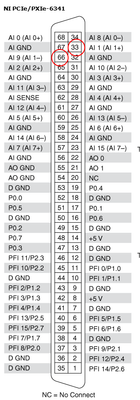
I have LV2012, NI PXIe-6341 and I have measured voltages at channels AI0:AI5 in RSE mode. It worked like a charm.
Then a need for measurement in differential mode emerged on channel AI1. The AI1- was wired on place, the initialization in LV was changed to set the channels as Differential. The channel AI1 was measurig correctly which was confirmed with a multimeter. But, of course the other channels that are still connected for the RSE mode are reading nonsense.
I found that it is possible to set a mode for every channel separately. I did so, but now the measurements on AI1 are all wrong (e.g. 0.12V instead of 0V, 0.50V instead of 0.06V). When I change settings back to all Differential, the AI1 is good again.
Could you please look into the code attached and share if you find anything? 🙂
10-17-2014 09:42 AM
- Mark as New
- Bookmark
- Subscribe
- Mute
- Subscribe to RSS Feed
- Permalink
- Report to a Moderator
Update:
The error is not occuring when the neighbour channel AI2 is set to Differential. Could that mean a crosstalk?
The error also disappears at high sampling rates. Above 40kS/s
10-17-2014 05:09 PM
- Mark as New
- Bookmark
- Subscribe
- Mute
- Subscribe to RSS Feed
- Permalink
- Report to a Moderator
You should probably read through this article from NI and determine if you are allowing enough time to settle between measurements (depends on your source impedance):
How Do I Eliminate Ghosting from My Measurements?
Keep in mind that the default convert clock rate might be faster than you think if you have configured a low sample rate. You can specify the convert clock rate explicitly if you need to using a DAQmx Timing Property Node.
However, given that the issue does not happen when AI2 is configured for differential (I'm assuming that AI2 is scanned after AI1--I can't open your VI as I'm presently using LV 2011) and given that increasing the sample rate does not make the problem worse as it would with ghosting... I'm suspicious that you might have encountered a bug which was previously reported on the forum here:
http://forums.ni.com/t5/Multifunction-DAQ/Analog-input-errors-when-using-multiple-channels-with-diff...
In the original reported behavior on that thread, using a different range on channel n+1 affected the measurement on the nth channel in the scan list. Perhaps changing the input terminal configuraiton is susceptible to this same issue. You could try inserting a "dummy" differential channel between AI1 and the rest of your RSE channels to see if this gives the correct result (the downside to this workaround is a lower potential maximum sample rate).
Best Regards,
10-20-2014 06:09 AM
- Mark as New
- Bookmark
- Subscribe
- Mute
- Subscribe to RSS Feed
- Permalink
- Report to a Moderator
Thanks John, you saved my nerves for the weekend.
I'm attaching the VI exported for LV11 if you are interested.
I start to believe it is the bug reported on the thread you linked. Below is a figure with a waveform chart of cca. 7k samples (40k sampling rate, 2000s/chan. buffer size, differential mode, range -10..+10V). There is a peak that repeats from time to time and spoils my measurement which is passed thru a Mean VI.
This is how it looks when the next scanned channel is set as differential too.
I tried to halve the convert clock rate (280112/2) and the sampling rate (40k/2). That increased the peak occurence, i.e. more errors. I also tried to insert a dummy channel in the scan sequence, which decreased the error.
My only solution so far is to take huge amount of samples (40k) and pass them thru Mean, which weights out the peak.
10-20-2014 09:41 AM
- Mark as New
- Bookmark
- Subscribe
- Mute
- Subscribe to RSS Feed
- Permalink
- Report to a Moderator
have a look at the median filter... nice to cut out spikes.
and for normal (or even) distributed (noisy) signals replacing the mean with a median of same length works also fine.....
Henrik
LV since v3.1
“ground” is a convenient fantasy
'˙˙˙˙uıɐƃɐ lɐıp puɐ °06 ǝuoɥd ɹnoʎ uɹnʇ ǝsɐǝld 'ʎɹɐuıƃɐɯı sı pǝlɐıp ǝʌɐɥ noʎ ɹǝqɯnu ǝɥʇ'
10-20-2014 05:07 PM
- Mark as New
- Bookmark
- Subscribe
- Mute
- Subscribe to RSS Feed
- Permalink
- Report to a Moderator
Hey cubz,
For a sanity check, can you confirm your wiring configuration? Are your AI- pins connected to AI GND?
10-21-2014 03:38 AM
- Mark as New
- Bookmark
- Subscribe
- Mute
- Subscribe to RSS Feed
- Permalink
- Report to a Moderator
Hi KBreezy,
well, I don't uderstand which AI- pins should be connected to AI GND?
Otherwise it looks Ok to me 🙂


