- Subscribe to RSS Feed
- Mark Topic as New
- Mark Topic as Read
- Float this Topic for Current User
- Bookmark
- Subscribe
- Mute
- Printer Friendly Page
Trigger rearm time on USB 6211
11-21-2013 09:35 PM
- Mark as New
- Bookmark
- Subscribe
- Mute
- Subscribe to RSS Feed
- Permalink
- Report to a Moderator
I am using a USB 6211 to generate raster waveform and digital trigger to drive the galvanormeter mirror. I just want to send one cycle of waveform for every trigger pulse. The problem is that it seems like the USB 6211 trigger rearm speed is limited to about 20 Hz, which is quite low. Is this correct?
Any solution?
11-25-2013 09:08 AM
- Mark as New
- Bookmark
- Subscribe
- Mute
- Subscribe to RSS Feed
- Permalink
- Report to a Moderator
Hi Beat
What do you mean by rearm speed? Are you stopping the task and restarting it? Because DAQmx Trigger will only be armed once, unless you enable the retriggertable property to rearm the trigger without stopping the task. Unfortunately this property is not supported by the USB 6211 for analog output tasks.
Take a look at this, it can help you with your application.
Regards
11-25-2013 09:41 PM
- Mark as New
- Bookmark
- Subscribe
- Mute
- Subscribe to RSS Feed
- Permalink
- Report to a Moderator
I might use the wrong word to explain it. What I mean by observing the behavior of the device when it was programmed as shown in the code is that no matter how fast my triggering clock was, there seem to be a certain period of time when the device did not accept any trigger pluse. That period of time was about 50 ms or about 20 Hz clock rate. The code worked as I expected it to be at trigger frequency less than 20 Hz. As soon as the clock speed pass 20 Hz, the extra pulse was not accepted.
One thing that I did to verify the 50 ms time limit was by sending 200 Hz of clockspeed and found that the one that close to 50 ms did trig the device.
Is there any example how to setup this device to surpass that trigger speed?
If not possible with the USB 6211, which DAQ device you would reccomend to achieve more than 100 Hz trigger speed, or even better for up to 200 Hz?
Thanks for your response : )
11-27-2013 09:09 AM
- Mark as New
- Bookmark
- Subscribe
- Mute
- Subscribe to RSS Feed
- Permalink
- Report to a Moderator
Hi Beat
The time you describe, when the device does not accept any trigger pulse is the time that takes for the task to be executed. While the task is being executed, the device won’t accept any other trigger pulses.
If I understood correctly you are wiring a clock signal to the PFI 3 line of the device which you defined as your trigger and you want to trigger the output task on every rising edge of this signal. It works for a frequency of 20 HZ. Is that correct?
11-27-2013 09:16 AM
- Mark as New
- Bookmark
- Subscribe
- Mute
- Subscribe to RSS Feed
- Permalink
- Report to a Moderator
11-27-2013 09:24 AM
- Mark as New
- Bookmark
- Subscribe
- Mute
- Subscribe to RSS Feed
- Permalink
- Report to a Moderator
12-02-2013 02:49 PM
- Mark as New
- Bookmark
- Subscribe
- Mute
- Subscribe to RSS Feed
- Permalink
- Report to a Moderator
Hi Beat
Can you share your code to try to reproduce the issue on my end?
01-17-2014 02:09 AM
- Mark as New
- Bookmark
- Subscribe
- Mute
- Subscribe to RSS Feed
- Permalink
- Report to a Moderator
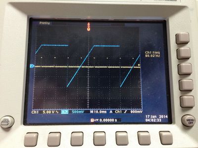
The labview code is attached. A wavefrom we would like to produce is a sawtooth, for example at 40 Hz sweep rate. The trigger pulse rate was set at 80 Hz. Please see an attatched picture for our result.
Thanks in advance.
03-24-2014 10:57 PM
- Mark as New
- Bookmark
- Subscribe
- Mute
- Subscribe to RSS Feed
- Permalink
- Report to a Moderator
Any new solution or comment? I still can not solve this issue.
03-27-2014 11:35 AM
- Mark as New
- Bookmark
- Subscribe
- Mute
- Subscribe to RSS Feed
- Permalink
- Report to a Moderator
I tried to open the attached vi but I could not run it. I got a broken arrow stating that the connector pane connections of the subVI (the Waveform Buffer Generation (multi).vi) do not match the way it is wired on this diagram, as if the original exmple had been modified; in fact, I noticed that your Waveform Buffer Generation (multi).vi from the trigger_sync_test.vi has on more input than mine.
Did you do any changes to that subVI? If so, you will also need to attach that VI.
National Instruments


