- Subscribe to RSS Feed
- Mark Topic as New
- Mark Topic as Read
- Float this Topic for Current User
- Bookmark
- Subscribe
- Mute
- Printer Friendly Page
Read/Write Function reads wrong value?
Solved!01-22-2014 04:09 AM
- Mark as New
- Bookmark
- Subscribe
- Mute
- Subscribe to RSS Feed
- Permalink
- Report to a Moderator
Hy,
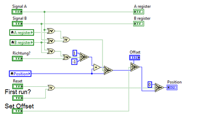
im using the NI Quadrature Encoder on my FPGA.
(http://www.ni.com/white-paper/6608/en/)
I add some inputs, so that its possible to set an offset value.
All in all the VI on the FPGA works fine with my encoder.
If i start the VI on my FPGA, the position value is 0, due to the "First run?" Element.
Now i used the Read/Write Control in a while loop on my Host VI to get the current value of the encoder.
After i start my host vi the position indicater shows allways the value "2".
If i use the highlight function, the value stays at "0".
Thats a really strange behavior, i dont know what can be the source of that problem.
All positionsoffset values are 0 and the encoder inputs on my 9401 module are connected with ground.
The position value is only written on the fpga, nowhere else.
Anyone got an idea for that?
Thanks a lot.
Solved! Go to Solution.
01-22-2014 04:23 AM
- Mark as New
- Bookmark
- Subscribe
- Mute
- Subscribe to RSS Feed
- Permalink
- Report to a Moderator
Without having looked at your problem too much I can see a race condition with your 'A Register' and 'B register' local variables. You don't know if the local variables will contain the value that the indicators have before or after receiving the 'Signal A' and 'Signal B' values. Highlighting may very well change that order.
Fast and easy way to check this is to put 'A Register' and 'B Register' indicators in a single frame sequence structure and wire the output of your topmost OR operator to its frame.
CLA
www.dvel.se
01-22-2014 04:26 AM
- Mark as New
- Bookmark
- Subscribe
- Mute
- Subscribe to RSS Feed
- Permalink
- Report to a Moderator
01-22-2014 04:57 AM
- Mark as New
- Bookmark
- Subscribe
- Mute
- Subscribe to RSS Feed
- Permalink
- Report to a Moderator
I will have a try with the feedback nodes.
01-22-2014 05:31 AM
- Mark as New
- Bookmark
- Subscribe
- Mute
- Subscribe to RSS Feed
- Permalink
- Report to a Moderator
Below is my whole code.
On FPGA Level erverything still works fine and the position is "0".
On Host i still get the position value "2".
New Sub VI on FPGA:
FPGA Top Level:
Host VI (new one for testing):
01-22-2014 05:38 AM
- Mark as New
- Bookmark
- Subscribe
- Mute
- Subscribe to RSS Feed
- Permalink
- Report to a Moderator
01-22-2014 07:03 AM
- Mark as New
- Bookmark
- Subscribe
- Mute
- Subscribe to RSS Feed
- Permalink
- Report to a Moderator
Hy,
FPGA is running the Indicater increases rapidly.
And also i tried the U8 Indicator, looks also fine.
I can't recognize any problem with that. But i still get no "0" as position value at the beginning.
01-22-2014 07:51 AM
- Mark as New
- Bookmark
- Subscribe
- Mute
- Subscribe to RSS Feed
- Permalink
- Report to a Moderator
01-23-2014 01:12 AM - edited 01-23-2014 01:14 AM
- Mark as New
- Bookmark
- Subscribe
- Mute
- Subscribe to RSS Feed
- Permalink
- Report to a Moderator
Well,
i connect both encoder input pins on crio side to ground.
So the signal level should be on a defined "0" level.
The Encoder signal follows the TTL spec.
01-23-2014 02:44 AM - edited 01-23-2014 02:49 AM
- Mark as New
- Bookmark
- Subscribe
- Mute
- Subscribe to RSS Feed
- Permalink
- Report to a Moderator
Mh, i found a new strange behavior.
I modified my FPGA VI as below.
If i set the "Input Enable" to false, the "false" value is given to the Sub VI with the encoder code.
On Host VI my position stays after running the VI at "0".
If I set the "Input Enable" to True, I read in the real Inputs to the Sub VI.
(But I connected them to ground!, so they should be also recognize as "false")
On Host VI the position switch to "2" after i start it.
Ok, next step was that i take a look on the host vi.
The FPGA use the real inputs, "Input Enable" is True.
If the loop counter reaches e.g. "7" the positions value changes to "2".


