- Subscribe to RSS Feed
- Mark Topic as New
- Mark Topic as Read
- Float this Topic for Current User
- Bookmark
- Subscribe
- Mute
- Printer Friendly Page
Graph data coming from an ADXL345 Accelerometer in LabView
01-10-2016 08:08 PM
- Mark as New
- Bookmark
- Subscribe
- Mute
- Subscribe to RSS Feed
- Permalink
- Report to a Moderator
Hi,
I have an ADXL345 Accelerometer. I want to graph data in LabView. How do I do that?
I already installed the Arduino Interface in my LabView. I've fixed my NI-VISA. My only problem is I do not know the proper wiring of the blocks as this is not just a simple AnalogRead.
01-10-2016 11:52 PM
- Mark as New
- Bookmark
- Subscribe
- Mute
- Subscribe to RSS Feed
- Permalink
- Report to a Moderator
Can you read in the data?
Mike...
Certified Professional Instructor
Certified LabVIEW Architect
LabVIEW Champion
"... after all, He's not a tame lion..."
For help with grief and grieving.
01-11-2016 01:13 AM
- Mark as New
- Bookmark
- Subscribe
- Mute
- Subscribe to RSS Feed
- Permalink
- Report to a Moderator
Hi, what tutorial should I be looking at?
What do you mean by "read in the data?"
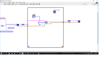
that's the snippet I followed but that's not complete. Honestly, I do not know if that's going to work. Don't mind the Waveform Graph.
01-11-2016 04:06 AM
- Mark as New
- Bookmark
- Subscribe
- Mute
- Subscribe to RSS Feed
- Permalink
- Report to a Moderator
01-11-2016 04:14 AM
- Mark as New
- Bookmark
- Subscribe
- Mute
- Subscribe to RSS Feed
- Permalink
- Report to a Moderator
Hi Jose,
it seems you send the measurement data from Arduino to serial port.
Just connect the Arduino to your PC and read the data from (PCs) serial port using VISA functions. Use the "Basic serial read and write" example VI as a starting point in LabVIEW!
01-11-2016 04:20 AM
- Mark as New
- Bookmark
- Subscribe
- Mute
- Subscribe to RSS Feed
- Permalink
- Report to a Moderator
I think he is referring to some basic LabVIEW tutorials. There are many free training resources which are linked to under 'looking for free training' on this page.
The screenshot you posted was way too small to see what you are doing. Post a larger screenshot or upload your VI so we can open it.
You will probably need to modify your Arduino code to output the accelerometer data over serial and then use NI-VISA to read the data in LabVIEW, decode the string containing your accelerometer values and then write them to a waveform chart.
If you really want to use the Arduino interface -
http://digital.ni.com/public.nsf/allkb/872C9DBFAB5F805C86257885005D2AC3
01-11-2016 05:17 AM
- Mark as New
- Bookmark
- Subscribe
- Mute
- Subscribe to RSS Feed
- Permalink
- Report to a Moderator
Hi, I forgot to mention that I changed something on the code that I posted.
Instead of:
const byte  spiclk=17;    // connect to ADXL CLK
const byte  spimiso=16;  // connect to ADXL DO
const byte spimosi=15;  // connect to ADXL DI
const byte spics=14;    // connect to ADXL CS
I change the pin assignment to anaog.
const byte  spiclk=A0;    // connect to ADXL CLK
const byte  spimiso=A1;  // connect to ADXL DO
const byte spimosi=A2;  // connect to ADXL DI
const byte spics=A3;    // connect to ADXL CS
I don't know if this means something aside from the pin assignment. I just thought that you need to know.
Thanks for all your replies. I will try what you suggest GerdW. Sam_Sharp, I will read them. Thanks! 🙂

