From Friday, April 19th (11:00 PM CDT) through Saturday, April 20th (2:00 PM CDT), 2024, ni.com will undergo system upgrades that may result in temporary service interruption.
We appreciate your patience as we improve our online experience.
From Friday, April 19th (11:00 PM CDT) through Saturday, April 20th (2:00 PM CDT), 2024, ni.com will undergo system upgrades that may result in temporary service interruption.
We appreciate your patience as we improve our online experience.
06-23-2014 01:36 PM
hi,
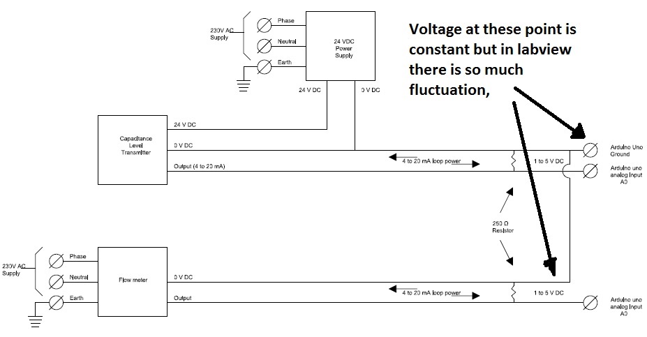
i have connected 1 to 5 V input to arduino which gives stable (O/P) from level transmitter.
Say at 50% it gives 3V Dc, when checked with multimeter.
But on labview it keeps fluctuating from 20% to 70% of level continiously.
I have used external 24V Dc power supply for Level transmitter and 250ohm resistor to convert 4 to 20mA signal to 1 to 5 VDc.
One wire is connected to analog input A0 and another to Arduino analog input ground.
Is it OK or i should do changes, is there any dampning circuit in this case.
Please suggest
Regards
mms79
Solved! Go to Solution.
06-23-2014 07:15 PM
Is your 4 to 20ma current loop coonected to ground at two separate points? Once at the 24 volt loop power suplly and once at the Arduino board, This may cause weird operation.
Or you may need to use an Instrumentation amplifier ssch as the following.
<http://www.techques.com/question/4-18588/Why-use-a-three-opamp-instrumentation-amplifier>
hhrh1818
06-27-2014 12:53 PM
Thanks hhrh 1818,
i have connected the transmitters with arduino as shown below (Also attached image).
is it necessary to use instrumentation amplifier, as i want to keep ckt as simple as possible.
please reply and suggest corrections.
Regards
MMS79
 .
.
06-27-2014 05:39 PM
Mostly I am baffled. But here are a couple of things to try. Do you still see the fluctuations if you connect only one of the two current loops to Arduino? Use an oscilloscope to inspect the signal. Is the signal fluctuating at a low frequency or is it power line noise or higher fervency noise?
hrh1818
07-01-2014 12:34 PM
I removed one flow loop, for doagnostic purpose and kept only Level loop.
checked connecting multimeter in AC Range and found 1.8V AC as well as, voltage rises as the level rises,
AC voltage rised up to 8.5V AC as level rised.
Also i checked connecting signal to oscilloscope, i found such kind of waveform.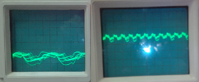
Also observed that two led ON and L glows dim as soon as level transmitter (capacitance Type) is connected to arduino without providing power to arduino(through USB from PC/Laptop).
it seems the error is incorporated due to level transmitter.
Is their any simple filter circuit which can work fine on such condition.
Can designing a low pass filter in labview will solve the issue.
Regards
MMS79
07-01-2014 08:40 PM
The low pass filter must be located between the loop sense resistor and the Arduino analog input pin. If you try to create a low pass digital filter in Labview you will have aliasing and saturation problems
Attached is a PDF showing my suggested low pass falter. It is OK to use polarized capacitors.
hrh1818
07-03-2014 10:12 PM
Thanks hrh1818,
Problem is solved and now getting stable level readings.
Regards
MMS79
