- Subscribe to RSS Feed
- Mark Topic as New
- Mark Topic as Read
- Float this Topic for Current User
- Bookmark
- Subscribe
- Mute
- Printer Friendly Page
Problem Setting Digital Pin I/O State using Labview with LIFA loaded on Uno
02-24-2014 01:50 PM
- Mark as New
- Bookmark
- Subscribe
- Mute
- Subscribe to RSS Feed
- Permalink
- Report to a Moderator
Hi guys, there's been a persistant problem I've been having setting the Digital I/O Pin states to high or low.
Basically, there are some pins that do not respond when set in labview to go high or low.
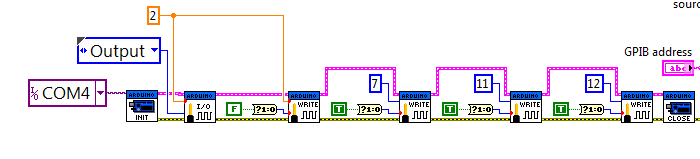
Notice that in the I/O block I have the constant '2' wired to it. Depending what number is wired to this I/O block it affects which pins will respond to commands.
If I remember correctly, pins 9 and 10 do not work when 2 is the constant, but if changed to 3 then pin 9 can be changed to either high or low.
Previously, I made a simple labview vi with a loop and switches on the front panel to manually set pins high or low and that is where I noticed that there is a problem with some pins not responding. Does anyone know why this is happening?
Another minor issue in addition to this one is I've noticed that the pins of the arduino are in random high/low states when first powered up and remain that way until after a labview vi is executed. Upon completion the pins return to their random states. I believe this to be something in the LIFA base coding itself, but after looking through the code trying to understand it, I do not see a way to make all the pins' default states to be low. Maybe someone more experienced with coding than I could discover the location to set the defaults as I've been unable to find anything from what I can understand from the code.
Help is very much appreciated.
02-24-2014 10:36 PM
- Mark as New
- Bookmark
- Subscribe
- Mute
- Subscribe to RSS Feed
- Permalink
- Report to a Moderator
1. When you use digital pins, you must always set the pin mode for how you plan on using the pin for each and every pin that you use. In the image above, you only set the pin mode for pin 2. There should be no dependency between pins and your experience is likely caused by not setting the pin modes correctly.
2. I know that there is at least one thread here about the default state of pins. IIRC, you need to add Arduino code to the firmware to set the pins. However, I don't think that this is always immediate so you may need to use pull-down resistors on each of the pins that have a critical dependence on the default state.
However, you should consider NOT using LIFA for you project because it is no longer officially supported by the author and will not be getting updates or bug fixes going forward. So, you should highly consider using LINX which is being developed by the original author of LIFA. You can find information about LINX at LabVIEWHacker.com
02-26-2014 01:27 PM
- Mark as New
- Bookmark
- Subscribe
- Mute
- Subscribe to RSS Feed
- Permalink
- Report to a Moderator
First, thank you for the reply.
The example I gave above was based off the example vi included with the LIFA for LED switching. In the example, only a single I/O was used and I just followed that example. It would be really helpful if this could somehow be coded in the firmware as default.
I will give searching another try for default pin states. Possibly I wasn't using the correct keywords when searching as I did not find anything of use.
I also will look into LINX, however, I do not really see any issues with using LIFA for my project unless of course these issues I have are specifically related to a bug in LIFA. The vi was created with a 2012 version of labview which most likely will not be upgraded and the equipment/circuits this vi operates were custom built and would have no further changes.
The equipment, circuits, and labview interface all work correctly and perform their intended operations using the pins that have controllable states. While the default pin states are not critical since nothing is energized until a few steps after the pin states are set, the annoying clicking at the beginning is really the only motivation for seeking a solution for the default pin states in the firmware. The switching components are only receiving microamps of current and therefore would not be detrimental to the lifespan of the switch contacts.
02-26-2014 04:02 PM
- Mark as New
- Bookmark
- Subscribe
- Mute
- Subscribe to RSS Feed
- Permalink
- Report to a Moderator
The example I gave above was based off the example vi included with the LIFA for LED switching. In the example, only a single I/O was used and I just followed that example. It would be really helpful if this could somehow be coded in the firmware as default.
I don't understand to what you are referring for being coded into the firmware (the statement highlighted in bold above).
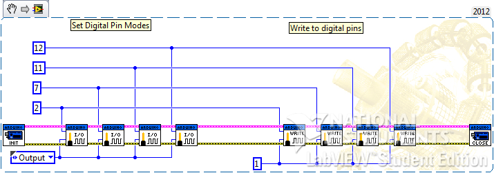
In the image in your first post, only pin 2 is set up correctly to be used because pins will default to INPUT mode (except pin 13 which defaults to OUTPUT). Pins 7, 11, and 12 are not set as outputs and therefore you cannot trust that it will output what out are requesting of it when you write to those pins. Here is an example that shows the initializing of all four pinsand writes a 1 to all of them (a 1 equates to HIGH):
I will give searching another try for default pin states. Possibly I wasn't using the correct keywords when searching as I did not find anything of use.
I remember helping someone with this issue and they were able to simply edit the firmware to set them to a certain state (by first setting their mode an then writing to it). This approach is not all that convenient because you have to edit the firmware everytime you want to change which pins you are using. One recommendation I read on a datasheet for Atmel was to use an external pull-up or pull-down resistor.
I also will look into LINX, however, I do not really see any issues with using LIFA for my project unless of course these issues I have are specifically related to a bug in LIFA. The vi was created with a 2012 version of labview which most likely will not be upgraded and the equipment/circuits this vi operates were custom built and would have no further changes.
LINX should run on any version of LabVIEW after 2011 (maybe 2010 even). If you would like to stick with LIFA, that is fine too.
The equipment, circuits, and labview interface all work correctly and perform their intended operations using the pins that have controllable states. While the default pin states are not critical since nothing is energized until a few steps after the pin states are set, the annoying clicking at the beginning is really the only motivation for seeking a solution for the default pin states in the firmware. The switching components are only receiving microamps of current and therefore would not be detrimental to the lifespan of the switch contacts.
Again, it seems that maybe pull-down or pull-up resistors(depending on the default state required) would work here.
02-28-2014 09:37 AM
- Mark as New
- Bookmark
- Subscribe
- Mute
- Subscribe to RSS Feed
- Permalink
- Report to a Moderator
"I don't understand to what you are referring for being coded into the firmware (the statement highlighted in bold above)."
What I mean by coded in the firmware is I was referring to the default states of the pins on the arduino. We load the labview interface code onto the arduino so that labview can work with the uC. The only ways I can see setting the default state of the pins when the arduino is first powered is either by altering/adding code to the labview interface code, or altering/adding code to the firmware if there is any to the uC itself.
"In the image in your first post, only pin 2 is set up correctly to be used because pins will default to INPUT mode (except pin 13 which defaults to OUTPUT). Pins 7, 11, and 12 are not set as outputs and therefore you cannot trust that it will output what out are requesting of it when you write to those pins. Here is an example that shows the initializing of all four pinsand writes a 1 to all of them (a 1 equates to HIGH):"
Yes, I see what you are saying. Following the example that was provided is how I came up with the blocks in the image.
"I remember helping someone with this issue and they were able to simply edit the firmware to set them to a certain state (by first setting their mode an then writing to it). This approach is not all that convenient because you have to edit the firmware everytime you want to change which pins you are using. One recommendation I read on a datasheet for Atmel was to use an external pull-up or pull-down resistor."
Editing the firmware is likely the solution I am looking for since pull-up/down resistors are not an option at this point and there's no reason pins would needed to be changed in the future. I've located your other post on here about the default pins and will see how that performs.
09-20-2014 09:16 AM
- Mark as New
- Bookmark
- Subscribe
- Mute
- Subscribe to RSS Feed
- Permalink
- Report to a Moderator
may i know how to code the firmware to control the default state of the pin on arduino...i wan off the led when the arduino is first powered...
09-20-2014 11:16 AM
- Mark as New
- Bookmark
- Subscribe
- Mute
- Subscribe to RSS Feed
- Permalink
- Report to a Moderator
The best that you can do without modifying LIFA is to simply set the pin to zero immediately after Init.vi. If that is not quick enough, the quickest you can set the pin state is to add it to the firmware in the setup function.
09-20-2014 11:30 AM
- Mark as New
- Bookmark
- Subscribe
- Mute
- Subscribe to RSS Feed
- Permalink
- Report to a Moderator
my problem is i need to set led off before i run the labview..if set the pin to zero immediately after Init.vi, it ll not work...
09-20-2014 01:45 PM
- Mark as New
- Bookmark
- Subscribe
- Mute
- Subscribe to RSS Feed
- Permalink
- Report to a Moderator
Use a diferent digital pin. Some are set low and some are set high at startup. Use a digital multmeter to check the state at startjup.
hrh212
