- Subscribe to RSS Feed
- Mark Topic as New
- Mark Topic as Read
- Float this Topic for Current User
- Bookmark
- Subscribe
- Mute
- Printer Friendly Page
Experimental aquaponics with Arduino and multiple sensors
10-18-2013 07:55 AM
- Mark as New
- Bookmark
- Subscribe
- Mute
- Subscribe to RSS Feed
- Permalink
- Report to a Moderator
Hi,
Take a look at the picture I have attached,
at the right side, there is a 500 lt tank (Buffer tank).

The system has 2 different stages, where the water flows in one part of the circuit until the Buffer Tank is full and then switches all the valves and irrorate the other part of the system until the marker on the Buffer Tank is reached and all start again.
I was thinking to use 2 microswitches (in the 500 lt. and 250 lt. position) to give the command to swich. I tried to put this solution on LabView but I can not come out with a solution........ do you?
Basically I think I need 2 Digital Inputs to give me a signal TF when the microswiches are pressed or released.
Coould you give me a spark of an idea?
10-18-2013 09:08 AM
- Mark as New
- Bookmark
- Subscribe
- Mute
- Subscribe to RSS Feed
- Permalink
- Report to a Moderator
andreaspi wrote:
Basically I think I need 2 Digital Inputs to give me a signal TF when the microswiches are pressed or released.
That is correct. You simply need to constantly poll the two switches and perform specific actions when either switch has changed.
10-18-2013 09:40 AM
- Mark as New
- Bookmark
- Subscribe
- Mute
- Subscribe to RSS Feed
- Permalink
- Report to a Moderator
Hi Nathan_B,
Nathan_B. wrote:
andreaspi wrote:
Basically I think I need 2 Digital Inputs to give me a signal TF when the microswiches are pressed or released.
That is correct. You simply need to constantly poll the two switches and perform specific actions when either switch has changed.
Yep, the thing is that I dont know how put this in a schematic way on LabView.......If it is one loop is ok..... more than this I am lost,,,,,,,,,. better sleep over it.
10-18-2013 11:51 AM
- Mark as New
- Bookmark
- Subscribe
- Mute
- Subscribe to RSS Feed
- Permalink
- Report to a Moderator
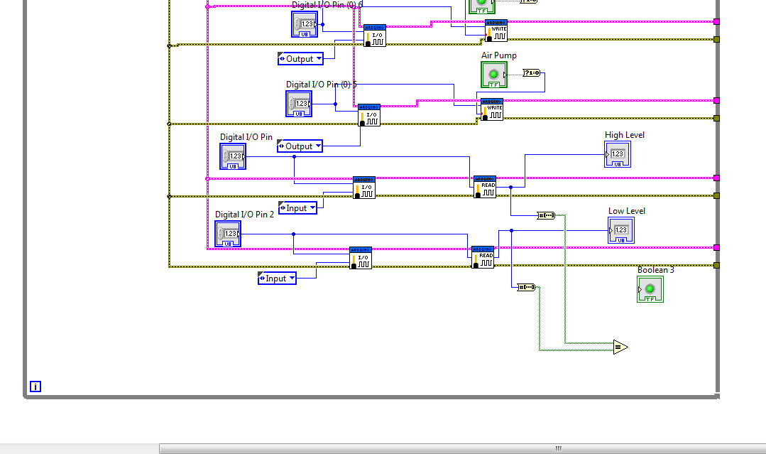
The first thing that I notice is that you don't want to use the byte to boolean array fucntion. Simply check if the value from the digital pin is not equal to zero to convert it to a boolean.
Other than that, I'm not really sure what you are having issues with. If the high leve switch is active then you have at least that level of liquid. If the low level switch is active then you have at least that level of liquid. So, if the high level is active then the low leve must also be active.
If you want to see the exact transition, between a switch being not active to active, you compare the current value with the previous value and look for: current value > previous value.
10-20-2013 02:16 AM
- Mark as New
- Bookmark
- Subscribe
- Mute
- Subscribe to RSS Feed
- Permalink
- Report to a Moderator
Hi Nathan_B.
Ok. two days of trying... and not a good result! Could you please give me another clue of the:
If you want to see the exact transition, between a switch being not active to active, you compare the current value with the previous value and look for: current value > previous value.
This morning have connected the 8 relays to the syste and I am impressed to see how nicely all was working. So now I am more motivated.
One more function it would be to have a timer that record the time between the two cycles (from when the High level Switch get activated to when the Low level switch get activated. Do you have a clue here to?
Have a good Sunday
Andrea
10-20-2013 05:29 AM
- Mark as New
- Bookmark
- Subscribe
- Mute
- Subscribe to RSS Feed
- Permalink
- Report to a Moderator
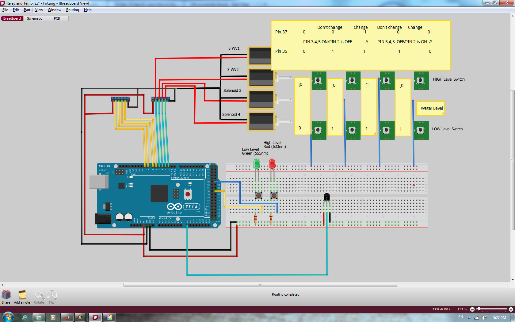
Hi,
Here a better way to explain part of my circuit....... Probably I am not seeing the problem from the right angle..........
10-20-2013 11:53 AM
- Mark as New
- Bookmark
- Subscribe
- Mute
- Subscribe to RSS Feed
- Permalink
- Report to a Moderator
This is how I check for a rising edge of a digital pin.

To get the falling edge, you should be able to change the > to a <. Also, I don't really understand your wiring diagram.
10-20-2013 10:34 PM
- Mark as New
- Bookmark
- Subscribe
- Mute
- Subscribe to RSS Feed
- Permalink
- Report to a Moderator
Hi Nathan_B,
yes, I agree, it was not a real wiring diagram, I just wanted to show the concept of High and Low and what is connected on my Arduino.
Between the Arduino and the Pumps or Solenoids I have 2 "4 Ch Relay +5VDC" that switch the power ON OFF. This is in place and working.
The Themperature Sensor is for now a normal Thermistor LM35, will be changed with 4 new one like this one:
https://www.atlas-scientific.com/_files/code/ENV-TMP-Arduino-Sample-Code.pdf
Thanks a lot for your schema, I will be exercising a bit on this.
I understand can be frustrating to communicate with someone that doasn't have a fraction of your knoledge about this stuff... Just to tell you I appreciate your effort.
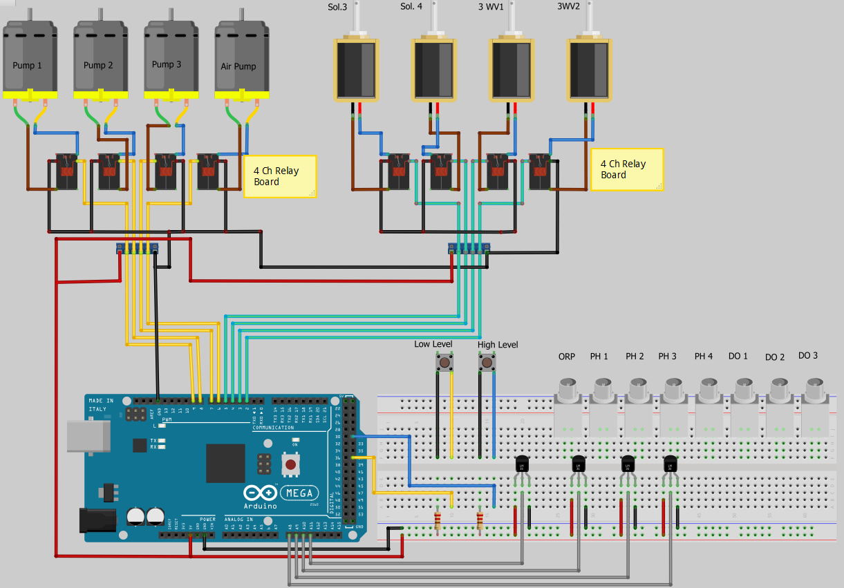
Here I have updated a bit my concept. All the probes are still not connected, I am waiting for the delivery from Atlas Scientific with all the Serial Converters.
All the best
Andrea
10-24-2013 03:02 AM
- Mark as New
- Bookmark
- Subscribe
- Mute
- Subscribe to RSS Feed
- Permalink
- Report to a Moderator
Ok, Package deliverd to my home......
Got all the parts:
Female BNCs, termianla, debugging units, Serial connectors
I am ready for some serious test.......
All the digital Outputs for the pumps and valves are working properly ! THANKS Nathan_B and hrh 1818!
I have setted up on the desk a copy of the system I have in the garden with
Arduino Mega,
Solderless plug in board
cables and sensors.........
I am starting my 'blind navigation' to assemble the project 
Please give me some indication on the right direction 
Will keep you posted.
hrh1818 wrote:
Hello Andrea,
To connect the sensors to an Arduino you will need the following components.
Seven Pre-assembled Female BNCs See:
<https://www.atlas-scientific.com/product_pages/components/bnc.html>
The BNC end connects to a PH or DO sensors. The other end will plug into a solderless breadboard.
Three solderless plug-in breadboards. See:
Breadboard Jumper Wires. See:
The PH Circuit board , DO Circuit board and Serial Port Connector plug into a Solderless breadboard. The breadboard jumper wires are used to connect the signals between a Pre-assembled female BNC, a Circuit Board, a Serial Port Connector and the Arduino Mega.
Ten Terminal blocks with screw terminals and with 2.54 mm pitch. See
<https://www.sparkfun.com/products/10571>
For connecting the temperature sensors to a solderless breadboard. You will need 3 for every 2 temperature sensors.
Optional but highly recommended.
For calibrating and testing the sensors without using an Arduino Mega.
A Debugger. See:
<https://www.atlas-scientific.com/product_pages/embedded/debugger.html>
Then free Atlas Desktop.
Optional, low priority.
The Arduino Rapid Development Shield. See:
<https://www.atlas-scientific.com/product_pages/components/arduino-shield.html>
A second Arduino Mega.
Spare PH And DO Circuit boards.
The object here is to have some test hardware available that can be used independently of the main hardware used for running the experiment.
Do you have an electronic technician available or have you done some soldering in the past?
Both the Serial Board Connectors and the Arduino Raid Development shield require soldering headers to the boards.
hrh18918
10-24-2013 09:24 AM
- Mark as New
- Bookmark
- Subscribe
- Mute
- Subscribe to RSS Feed
- Permalink
- Report to a Moderator
My first step would be to test the sensors with the debugging device so that if issues do arise, you can be sure that it's not the sensor board that is causing the problem. If all goes well with this, I would start working with the Arduino. I would work with only a single sensor without the serial multiplexer and get that communication working for each of the types of sensors. Then, add in the necessary code to use them on the multiplexers.
